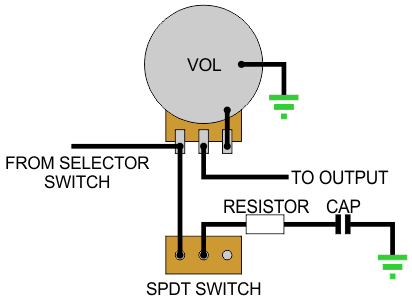
Tone miniswitch instead of pot?

C

Cederick

Guest
I'm thinking about having a miniswitch for tone-control instead of a pot, both because of the looks and because I rarely fine-tune the tone knob very much anyway.

So I wonder if this could work?

Otherwise, a miniswitch for toggling direct into output or through a tone knob is also an alternative that could work for me. I would have all adjustment possibilities, but I could still leave the tone knob in a good position and then use the switch to bypass it because with a non-step knob its almost impossible to find the exact spot again.

2nlwhap.jpg
 
You  still need a resistor in series with the cap to ground.  set the tone pot then measure it. The other issue is pot holes are bigger than the one for the miniswitch.
 
swarfrat said:
You  still need a resistor in series with the cap to ground.  set the tone pot then measure it. The other issue is pot holes are bigger than the one for the miniswitch.
Hmmm, I dont understand that, haha. I'm totally green on electroinics

But I drill new holes, I only have one volume and one LP switch at the moment. It's a Warmoth Soloist with Charvel live HH config
 
l'll draw it up later if someone doesn't beat me to it. But without some resistance your tone switch is gonna suck all audio signal down a black hole.

 
Okay, thanks for the info. Awaiting fancy wiring diagram  :hello2:
 
if i read your drawing right, you have the signal in series with the cap to the output since it appears to be a bypass of some kind, there is an easier way to do this though but i'm not sure it's actually what you want to begin with so i'll skip the tutorial. this is a good way to cut bass. what you want is to clamp the signal to ground with a cap (or is it?). you could add a resistor if there is a particular tone position you like using a certain sized cap. you could also use two caps or a cap and two resistors, or w/wo resistor and an on/off/on switch to get different discrete levels of tone. there are also tone circuits with a rotary switch available that give i think 17 discrete tone settings. (look up stellar tone tonestyler).

 
Your existing diagram is way too complicated. All you need to do is use one pole and one throw to place the capacitor parallel to the signal. The resistor then goes in series with the capacitor.

The wiring should be like this, but WITHOUT the inductor.
8625896806_47f44deae2_o.png
 
line6man said:
Your existing diagram is way too complicated. All you need to do is use one pole and one throw to place the capacitor parallel to the signal. The resistor then goes in series with the capacitor.

The wiring should be like this, but WITHOUT the inductor.
8625896806_47f44deae2_o.png

I dont understand this  :(
 
Cederick said:
line6man said:
Your existing diagram is way too complicated. All you need to do is use one pole and one throw to place the capacitor parallel to the signal. The resistor then goes in series with the capacitor.

The wiring should be like this, but WITHOUT the inductor.
8625896806_47f44deae2_o.png

I dont understand this  :(

There is no possible way to make it any simpler.

Fat Pete said:
How about this?

toneswitch.gif

Yep.
 
No I dont want a tone knob, only a switch with three tone "levels".

Mini switch position 1: Full tone
Mini switch position 2: Medium tone
Mini switch position 3: Dull tone

No knob :icon_biggrin:
 
There's no tone knob in the drawing Pete gave you. It's either no tone control or whatever filter your resistor/capacitor choices provide, which is what you originally asked for.
 
For that you'll need a SPDT switch, and two caps. They can share the resistor. And unless you look a looooong time you're likely going to have the middle position being "no tone control (full bright) rather than at one end. Just because that's whats commonly available.
 
Cederick said:
No I dont want a tone knob, only a switch with three tone "levels".

Mini switch position 1: Full tone
Mini switch position 2: Medium tone
Mini switch position 3: Dull tone

No knob :icon_biggrin:

For this, you will want a SP3T switch. That would be a DPDT On/On/On with an external jumper wire.

The question is how you will achieve the settings you want. "Full tone" would be a bypass position, whereas the other two can be achieved in different ways. You can use one capacitor with two resistors, or you could use two capacitors with no resistors.
 
take fat pete's drawing, swap the two leads on the spdt switch then add another resistor onto the spdt switch going from the left most contact to the right most (or another capacitor, you could do different variations on this). it should be an on/off/on switch. the middle position will be no influence from the tone, then on position will be one reisitor + cap to ground and this will be the fatter sound with less treble. the other position will have more resistence to ground like a high number on the tone knob. if you chose to add a cap instead it will act like the same knob position but on a control with a small cap also being brighter.

if you have an on/on/on variant of the switch the extra parts will go to ground. in this case you would want a pretty big resistor for the bright position because there would be no off position and the two resistors and/or caps would need to be very different values. the middle position would be be fattest position having the two alternative tone circuits in parallel to each other bleeding treble on both similtaniously. then the outer positions would be different levels of influence. this could also have different layouts. you could use a single cap and fork 2 reisistors off of it to the outer contacts of the switch or you could have 2 resistors and 2 caps.

 
That brings us almost full circle... 270 degrees to be more precise. (aka tone pot infinitely variable between two values).  If the goal is a bang bang switch, more is not necessarily better.
 
Problem with petes diagram is that I dont understand it

I really need a kindergarden type of instruction because I know VERY little about electronics.

I understand the other picture including actual images of pots and stuff, but if there's nothing like that I dont understand it  :tard: :toothy12:
 
Without meaning to be unkind cederick, if you don't understand then learn a little. This stuff is one step up from a battery and a lightbulb - it really isn't difficult.

The simple on/off tone switch isn't a bad idea at all but you really need to experiment to actually get something that works for you - no point . Get some alligator clips, some wire and some different capacitors and resistors and just try stuff.
 
Back
Top