You are using an out of date browser. It may not display this or other websites correctly.
You should upgrade or use an alternative browser.
You should upgrade or use an alternative browser.
My latest little project
- Thread starter mayfly
- Start date
mayfly
Epic Member
- Messages
- 9,173
So I re-did my VA calculations and I found the error. Here's what I did:
transformer VA is essentially secondary volts * max current of the windings.
At 100W into 8 ohms, current required is 3.5A (not including any losses in the amplifier. Yes I know this is a simplification. Those heatsinks do get hot).
So, this means with a transformer secondary of 22 V, the VA required is 22 * 3.5 = 77VA.
This is wrong.
The transformer secondary voltage as used in the calculation is not 22V. It's 44V with a centertap. I confirmed it with several books and the hammond tech notes: Required VA rating is 44V * 3.5 = 154.
Sooo my transformer is about half as big as it should be. This is bad Just glad I didn't toast the windings during my tests! I believe I need to retire those particular transformers...
Onward!
transformer VA is essentially secondary volts * max current of the windings.
At 100W into 8 ohms, current required is 3.5A (not including any losses in the amplifier. Yes I know this is a simplification. Those heatsinks do get hot).
So, this means with a transformer secondary of 22 V, the VA required is 22 * 3.5 = 77VA.
This is wrong.
The transformer secondary voltage as used in the calculation is not 22V. It's 44V with a centertap. I confirmed it with several books and the hammond tech notes: Required VA rating is 44V * 3.5 = 154.
Sooo my transformer is about half as big as it should be. This is bad
Onward!
mayfly
Epic Member
- Messages
- 9,173
alright! Regarding thermals and transformer power I decided to take a step back and start from first principles. From the LM3886 datasheet the average power dissipation of the chip amp should be:
Pave = (Vopk / Rl) * (Vcc / Pi - Vopk / 2), where
Vopk = Vcc / Pi, Vcc = 52, and Rl = 8
Plug all this in and you get 17W of dissipation in the LM3886 right? Wrong it turns out! Diving into things a bit more I determined that when you operate in bridged mode you have to divide the load resistance in half, conceivably because each side of the bridge works against the other when pushing current into it. This means that the actual dissipation in the LM3886 is 2 * 17 = 34W. Times two because there are two of them.
That's a lot more that I originally thought.
So, looking at the VA requirements of the transformer, I now have to power 100W of output, and 34W x2 for the pair of LM3886 chip amps. So the transformer needs to supply 154 + 68 = 222W. But it's actually more because of transformer losses. A rule of thumb that I've seen kicked around is VA = 1.1 * power. This means that the VA of our transformer needs to be 222 * 1.1 = 244.
That's a lot more that I originally thought!
Now on to the heatsink. With these new dissipation numbers in hand, we can do some thermals.
From the data sheet, the maximum internal temp of the LM3886 die (Tjmax) is 150DegC. And our simple thermal equation is Power = (Tjmax - Tamb) / Thetaja, where Tamb is the temp of the room (I chose 25DegC), and Thetaja = Thetajc + Thetacs + Thetasa. I'm really starting to want some special symbols here.
The data sheet says Thetajc = 1Deg/W, and I'm using 0.2 Deg/W for Thetacs. Doing some algebraic manipulation that I don't feel like typing the Theta of the heatsink that I need to dissipate 68 watts of power at 25 Deg ambient needs to be 0.63 DegC/W. That's a lot smaller than the 3.3 DegC/W that I originally calculated!
Stay tuned. More to come. Don't think 100W monoblocks will be integrated into the speaker bases though...
P.S. If you find a problem with my calculations, please let me know!
mayfly
Epic Member
- Messages
- 9,173
Status report! Well, there's good news and bad news.
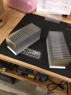
First, here's where we are at. With the new VA and dissipation numbers, new parts were sourced and the amp was re-built. A 0.63 Deg/watt heatsink is HUGE!!

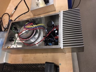
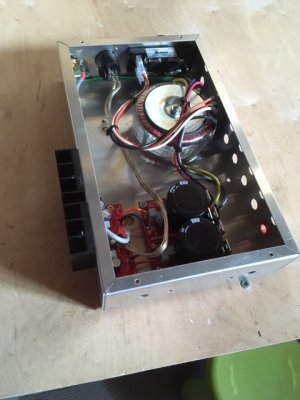
Here's a shot of the re-built amp with a 225 VA transformer:

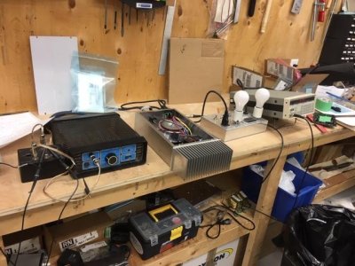
and here's the test rig. Off screen is the scope and the THD analyzer:

So, the results are good and bad. The good part is the amp now puts out a solid 100W of power! Yay! The bad news is that sustained 100W operation toasted the bridge rectifier that I had on there. Not so Yay! Digikey to the rescue with an upgraded bridge which I managed to bodge on there, but it needs a board spin to do it right (new bridge needs a heatsink). With the new bridge sustained 100W at 1KHz seems to be no problem.
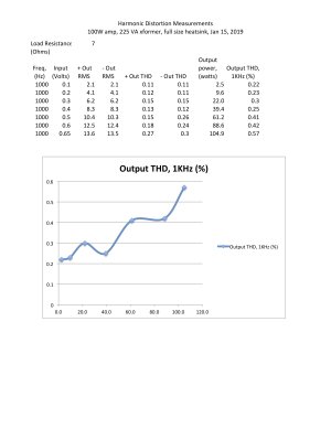
Now the bad news. First - it's huge! No way that's gonna fit under the speaker . Second, THD measurements are disappointing. Don't get me wrong, they are way better than before, but they still kinda suck:

Given the excellent THD of the 50W version, and given 0.1% THD was just barely acceptable in the 1970's, I think the 100W bridged chip amp beast is a dead end.
Was fun though!
Currently the stereo is run using a big crown PA amp, which is big and ugly. I think for the short term we'll switch to the small 50W prototype and see how that runs.
First, here's where we are at. With the new VA and dissipation numbers, new parts were sourced and the amp was re-built. A 0.63 Deg/watt heatsink is HUGE!!
Here's a shot of the re-built amp with a 225 VA transformer:
and here's the test rig. Off screen is the scope and the THD analyzer:
So, the results are good and bad. The good part is the amp now puts out a solid 100W of power! Yay! The bad news is that sustained 100W operation toasted the bridge rectifier that I had on there. Not so Yay! Digikey to the rescue with an upgraded bridge which I managed to bodge on there, but it needs a board spin to do it right (new bridge needs a heatsink). With the new bridge sustained 100W at 1KHz seems to be no problem.
Now the bad news. First - it's huge! No way that's gonna fit under the speaker
Given the excellent THD of the 50W version, and given 0.1% THD was just barely acceptable in the 1970's, I think the 100W bridged chip amp beast is a dead end.
Was fun though!
Currently the stereo is run using a big crown PA amp, which is big and ugly. I think for the short term we'll switch to the small 50W prototype and see how that runs.
Attachments
S
swarfrat
Guest
Cool beans. I just got a plastic spaghetti maker. Once I figure out how to print actual parts with it, I have a tuning port for my bass drum I'm trying to print. (Someone sells a $45 plastic duct, but it's only in 4" dia, and would require me to buy a new $45 head, as my 26" bass drum already has a 6" hole in it. So I bought a $200 printer instead - because that's what DIY guys do.) Your bump non-flutter ducts have my interest - maybe I'll print the enclosure for my kid's pi-radio project
mayfly
Epic Member
- Messages
- 9,173
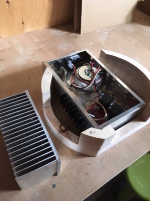
Update! Decided to whip up 50W mono-blocks instead. Using a generic LM3886 circuit and a 50VA transformer, with the heatsink hanging off the side this time:

Even though my calculations say that the small heatsinks are large enough, they don't stick out the side of the enclosure! Might switch to the big ones just to get the fins out. And no, the fins are too dull for kitchen appliances

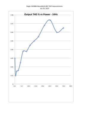
After initial power up, I wanted to see what this monoblock could do! I have all the test gear, so I spent some quality time in the lab. The amp actually hit clipping at only 35W. Here's the THD plot vs power output:

I'm liking the THD, which is really reasonable. Until you hit 35W that is - then things go to hell pretty quickly.
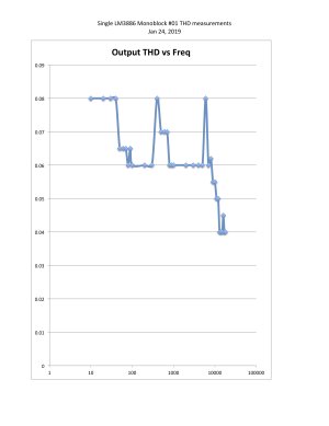
Decided to have a look at THD over the frequency range at just under clipping, and here's the chart:

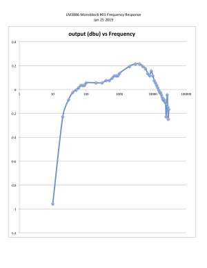
Still looks pretty good! So today my eldest son and I measured the frequency response. Here's what it is from 10Hz to 30KHz.

That looks pretty good as well! Surprised the low end is as good as it is. Things start getting a little crazy above 20KHz mind you...
So in summary - the single LM3886 amp is pretty good! Although a little down on power...
Even though my calculations say that the small heatsinks are large enough, they don't stick out the side of the enclosure! Might switch to the big ones just to get the fins out. And no, the fins are too dull for kitchen appliances
After initial power up, I wanted to see what this monoblock could do! I have all the test gear, so I spent some quality time in the lab. The amp actually hit clipping at only 35W. Here's the THD plot vs power output:
I'm liking the THD, which is really reasonable. Until you hit 35W that is - then things go to hell pretty quickly.
Decided to have a look at THD over the frequency range at just under clipping, and here's the chart:
Still looks pretty good! So today my eldest son and I measured the frequency response. Here's what it is from 10Hz to 30KHz.
That looks pretty good as well! Surprised the low end is as good as it is. Things start getting a little crazy above 20KHz mind you...
So in summary - the single LM3886 amp is pretty good! Although a little down on power...
Attachments
S
swarfrat
Guest
I saw this project after I'd ordered my 3D printer and the thought of anechoic (for lack of a better term) ducts intrigued me. But I said - I wonder how I'd do that?
Turns out the printer does it for you:

Turns out the printer does it for you:

ByteFrenzy
Hero Member
- Messages
- 1,177
Still weird that THD on the 100W version was that bad. I'm wondering if small individual differences between the LM3886 could cause two of them in a bridging setup to do that. Matching pairs of them could be a solution in that case.
mayfly
Epic Member
- Messages
- 9,173
Well, in bridged mode the load effectively drops to 4 ohms and the datasheet says that lowering the output impedance increases THD. That and (and I admit I could be doing this wrong, but from what I've read it's correct) I added the separately measured THDs for each side of the bridge to get the overall THD on the 100W versions. Can't test the bridged outputs together because one side of analyzer is grounded don'tchaknow.
BigSteve22
Hero Member
- Messages
- 2,798
They look great! Congrats Brother, beautiful result! :cool01:
Similar threads
- Replies
- 6
- Views
- 604
- Replies
- 8
- Views
- 967


