You are using an out of date browser. It may not display this or other websites correctly.
You should upgrade or use an alternative browser.
You should upgrade or use an alternative browser.
My latest little project
- Thread starter mayfly
- Start date
DarkPenguin
Senior Member
- Messages
- 370
Time for a sub?
BigSteve22
Hero Member
- Messages
- 2,798
Ambitious! But why design your own shrink wrapping? :icon_scratch:Mayfly said:update. Loads of acoustic design, simulation, and a lot of quality time with solidworks has yielded the next stage of this project.
mayfly
Epic Member
- Messages
- 9,174
BigSteve22 said:Ambitious! But why design your own shrink wrapping? :icon_scratch:Mayfly said:update. Loads of acoustic design, simulation, and a lot of quality time with solidworks has yielded the next stage of this project.
mayfly
Epic Member
- Messages
- 9,174
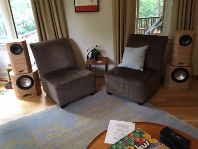
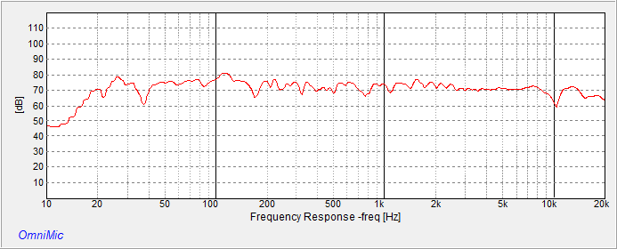
here's the finished product. Two designs: One on the left with a port, and one on the right with a passive radiator (mounted on the right hand side). Both utilize two-channel Hypex plate amps with DSP crossovers. Both measure flat to 20Hz and have a very impressive response, with the one with the port slightly better. But - something is wrong. They sound 'funny'.
I crossed over between the subs and the tops at 400Hz. I think I need to lower that.

Will report back. But here's the measured frequency response: Phase response looks ok at the crossover point, so I don't think I have a phasing issue... More later

I crossed over between the subs and the tops at 400Hz. I think I need to lower that.
Will report back. But here's the measured frequency response: Phase response looks ok at the crossover point, so I don't think I have a phasing issue... More later
Attachments
DarkPenguin
Senior Member
- Messages
- 370
"funny" how?
mayfly
Epic Member
- Messages
- 9,174
It's hard to describe, but here goes: let's say that you're listening to a song you really know well, like "here comes my girl" from Damn The Torpedoes.
Then you notice that the vocals sound like they are in the background much more. Then you notice that you can only hear the reverent sounds of those vocals; like if they only mixed with the wet sound from the reverb and did not include any dry sound. But the drums are nice and crisp (which is the reason why you're listening to this song in the first place), and the bass guitar is nice and clear. WTF?
Imagine yourself sitting there listening to this... If you're like me, you say: "wow - that sounds.... funny..."
mayfly
Epic Member
- Messages
- 9,174
Found it. I had placed a sub sonic filter in the DSP, centered at 10Hz. I used a 12db/octave linkwitz/riley filter - which would have been just fine...
... if I remembered that the 12db L/R filter has a 180Deg phase shift in the passband.
I removed the filter and also moved the crossover point to 200Hz. Sounds a lot better. Now why the hell didn't I see that on the phase plot??
... if I remembered that the 12db L/R filter has a 180Deg phase shift in the passband.
I removed the filter and also moved the crossover point to 200Hz. Sounds a lot better.
BigSteve22
Hero Member
- Messages
- 2,798
Yeah, what he just said! Not that I have any idea what you just said, but I'm glad you found your problem. That's an outstanding looking pair of speakers, it would be a shame for you to not be completely happy with the fruits of your labor! :glasses9:Mayfly said:Found it. I had placed a sub sonic filter in the DSP, centered at 10Hz. I used a 12db/octave linkwitz/riley filter - which would have been just fine...
... if I remembered that the 12db L/R filter has a 180Deg phase shift in the passband.
I removed the filter and also moved the crossover point to 200Hz. Sounds a lot better.Now why the hell didn't I see that on the phase plot??
rgand
Epic Member
- Messages
- 5,934
Mayfly said:Found it. I had placed a sub sonic filter in the DSP, centered at 10Hz. I used a 12db/octave linkwitz/riley filter - which would have been just fine...
... if I remembered that the 12db L/R filter has a 180Deg phase shift in the passband.
I removed the filter and also moved the crossover point to 200Hz. Sounds a lot better.Now why the hell didn't I see that on the phase plot??
LOL, I wish I knew more about the electronics side of things. Here's what I could understand:
:laughing11:Mayfly said:Found it. ... ...
... ...
... ... Sounds a lot better. ... ...
Looks great! Congratulations on getting it all working right. What a fine set of speakers.
mayfly
Epic Member
- Messages
- 9,174
rgand
Epic Member
- Messages
- 5,934
:icon_thumright: :icon_thumright: :icon_thumright: :icon_thumright: :icon_thumright:Mayfly said:
I like the site. The 360 degree viewer is really nice. I hope this is totally successful for you.
BigSteve22
Hero Member
- Messages
- 2,798
Very impressive! Good luck with your patent application, they certainly look unique to me. :headbang:Mayfly said:...oh if you're interested, Check this out:
http://www.mayflyaudio.com
DarkPenguin
Senior Member
- Messages
- 370
Cool. Now make a "tonewood" version of them and sell them for $40k.
mayfly
Epic Member
- Messages
- 9,174
More on this little adventure. It turned out that I could not drive the Hypex modules from my stereo preamp. Well, "stereo preamp" is kind of a stretch - it's a passive 'preamp' that I built years ago, essentially containing a stereo switch and a potentiometer. All unbalanced, output impedance about 50K. Output level matches the input level, which is -10dbu 'consumer' levels from the CD player, photo preamp, etc.
The Hypex modules have balanced inputs at 'pro' levels (+4dbu) and fairly low impedance. The passive 'preamp' didn't have the guts to drive them. In addition, although you can adjust the gain on the Hypex modules up to +12db or so to make up the difference between consumer and pro levels, the modules have a lot of hiss at those gain levels. I didn't like it.
So instead of going out to the store and buying a preamp with balanced outputs, I decided to make my own! Design goals were:
1 - High impedance inputs.
2 - Balanced outputs with lots of drive capability.
3 - Nice feeling volume control.
4 - 5 or 6 inputs, selected with a rotary switch.
5 - 17db of gain. This is to take the signal from consumer to line levels, with more besides to drive the amps.
6 - Stupid high audio quality. That is, as best as you can get no matter the cost.
7 - Well behaved on power on and off. That is, no thumps and bangs when you turn the thing on or off - especially when directly connected to power amps.
8 - 1 RU box. Black, nice engraving.
9 - power supply from a typical wall wart.
More to come...
mayfly
Epic Member
- Messages
- 9,174
The Design.
I decided to keep things as simple as possible by running the audio through the input selector and volume control and getting the quality up by just using good quality physical components. To that end I selected a Greyhill two pole 6 position switch with gold contacts for the input switch, and an Alps 27mm stereo potentiometer for the volume control.
For the audio path I figured I would stick with op-amps, but I knew that using my usual TL072's would not cut it. I had been reading a lot of books from Douglas Self, who gets excellent results from the good old NE5532, so that's what I picked. The only problem with the 5532's are that they have bipolar inputs. No, not that type of bipolar. The issue with bipolar inputs is that there are significant input bias currents, which can cause output offset voltages, clicks in switches, and noise when you turn pots. None of that would be acceptable left as is, so those issues were resolved using input bias resistors and inter-stage coupling caps.
For the outputs, I chose the balanced line drivers from THAT corp. But from previous designs I knew that these could make pretty big thumps when the power was pulled. Figured I could solve that with relays on the output that detect power shut-off.
Finally I wanted to use +/- 15V supply rails for lots of headroom. But you can't buy a wall wart that gives you that - they all just give a single DC supply. So I figured I could use TI's new(ish) 'rail splitter' thingy (TLE2426) to create a ground between the plus and minus outputs of the wall wart. Just needed to ensure that the wallwart was a floating type.
mayfly
Epic Member
- Messages
- 9,174
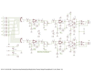
ok! Here's the main design:

Inputs go into the switch, then into the first coupling cap. This is a polypropylene number sized to give a 3db down point at 1.6Hz (remember that stupid audio quality goal?). The resistor on the other side's main purpose is to provide those bias currents for the op-amp stage. The opamp is set to provide a gain of 11.3db. I figured the big gain step should come before the volume control as the volume would reduce any hiss that this stage might cause. Turned out to be totally unnecessary.
From there it goes into another polypropylene cap and then into the volume pot. This cap had to be sized much larger than the previous stage as the volume control is fairly low impedance. It could have been bigger actually, but 4.7uf is the largest cap that Panasonic makes in the poly-prop series and I didn't want to use polyester (cheap suit - cheap sound - don'tchaknow). The volume control is dual-footprinted just in case I could not get the preferred Alps part - a bourns pot fills the role of second source.
After the volume control, it goes into the driver stage for the output chips. The THAT Corp chips have a surprisingly low input impedance, which means you can't drive them from the pot. Annoyingly, the input impedance is so low that if you were to use a coupling cap, the cap would have to be STUPID large to have a reasonable bass response, so I decided to direct-couple it with the driver stage. Now since the driver stage is another 5532, it meant I had to balance the input impedances to eliminate offset voltages. This is the purpose of the input resistor on the positive leg, and why it's set to 47k instead of something larger. The 47k meant that I needed a large-ish cap driving it to get a reasonable 3db point of 1.3Hz. Another Panasonic poly-prop cap fits here.
Last are the relays that ground the outputs (and disconnect them from the THAT corp drivers) when we detect the loss of the power supply. More on that later!
Attachments
Similar threads
- Replies
- 6
- Views
- 616
- Replies
- 8
- Views
- 981


