You are using an out of date browser. It may not display this or other websites correctly.
You should upgrade or use an alternative browser.
You should upgrade or use an alternative browser.
My latest little project
- Thread starter mayfly
- Start date
ByteFrenzy
Hero Member
- Messages
- 1,177
Interesting use of the term 'we'.
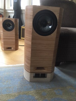
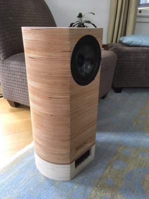
Can you move the heatsinks to the back of the amps along with the connectors?
Can you move the heatsinks to the back of the amps along with the connectors?
DarkPenguin
Senior Member
- Messages
- 370
Mayfly said:DarkPenguin said:So are the monoblocks your design or a kit or based on something?
Glad you asked! They are my own design. I'll post the schematic and PCB layout when I have a chance.
Oh! Well then I guess I'll have to learn how to make a pcb on my cnc.
ByteFrenzy
Hero Member
- Messages
- 1,177
Cagey said:Maybe you didn't see this picture. Might be able to fit a pilot light back there, but not much else.
Oh yes, I did, but moving the sinks is the only way to de-clutter the front. It would require a different housing for the amps, but there seems to be room inside the speaker bases to have those both a bit higher and wider. The socket for the speaker connection could also move to the side of the housing, keepng that connection entirely inside the speaker base.
mayfly
Epic Member
- Messages
- 9,175
ByteFrenzy said:Cagey said:Maybe you didn't see this picture. Might be able to fit a pilot light back there, but not much else.
Oh yes, I did, but moving the sinks is the only way to de-clutter the front. It would require a different housing for the amps, but there seems to be room inside the speaker bases to have those both a bit higher and wider. The socket for the speaker connection could also move to the side of the housing, keepng that connection entirely inside the speaker base.
I think I can visualize this. Might be worth a shot - or 1/2 an hour with pencil and paper
mayfly
Epic Member
- Messages
- 9,175
So I was thinking that if I had connectors on both sides, I might just be able to connect everything then drop it in from the top. Unfortunately even the low profile speakon connectors are too long (I'm a Neutrik guy).
But - then I saw this baby:

Maybe we have something here...
But - then I saw this baby:

Maybe we have something here...
new-killer-star
Senior Member
- Messages
- 267
I have Vienna acoustics mahlers, their base is rectangular and cantilevered... I realize yours don’t angle back like that but you could use shadow or even speaker grill cloth to hide the vents if they have to be in front.
mayfly
Epic Member
- Messages
- 9,175
Gentlemen,
I think I've got a mechanical design for the modified amps. Heatsinks out the the back. Cables out the side. More to come.
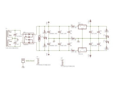
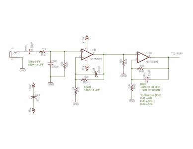
In the mean time, here's the schematics for my home brew 100W monoblock amps:
The power supply is pretty typical linear number. The +/- 30V rails are for the power amps, and the regulated +/- 15V rails are for the small signal stuff. I loaded up with caps of all sorts! Gotta love those stupid large panasonic parts. The weird thing that looks like a resistor just past the bridge is a varistor. The idea is that if it goes over it will trip the fuses that are on the other side of the transformer. Something new that I did is run separate grounds for the power supply/amp (0V) and the low signal stuff (GND) with a 2R2 resistor between them. The unit is grounded on the low signal side, allowing the 0V net to rattle as much as it likes without screwing up the noise floor. It works quite well - the amps are dead quiet!

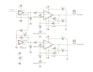
For the power amp I totally cheated: I used the wonderful LM3886 parts running in bridge mode for 100W into 8 ohms. They are set for about 21db of gain. These chips are great - I can't say enough about them. There are bandwidth limiting filters in there as well - the 3db points are noted on the schematic. IC7B is the inverter for the 'minus' side of the bridge. I decided to use NE5532 op amps everywhere after reading a bunch of books by Douglas Self. He's pretty keen on them.

The input stage I cribbed from Linkwitz. There is also a baffle step compensator with gives 3db of boost on anything below about 50Hz. Turns out that this is totally unnecessary - the speakers measure very flat (well - as well as you can measure them in a typical room) to 35Hz. I suspect that the round shape has eliminated the need for the compensation, which is pretty cool.

I'm listening to this rig as I type this (New Pornographers - Challengers). I really like it!!
I think I've got a mechanical design for the modified amps. Heatsinks out the the back. Cables out the side. More to come.
In the mean time, here's the schematics for my home brew 100W monoblock amps:
The power supply is pretty typical linear number. The +/- 30V rails are for the power amps, and the regulated +/- 15V rails are for the small signal stuff. I loaded up with caps of all sorts! Gotta love those stupid large panasonic parts. The weird thing that looks like a resistor just past the bridge is a varistor. The idea is that if it goes over it will trip the fuses that are on the other side of the transformer. Something new that I did is run separate grounds for the power supply/amp (0V) and the low signal stuff (GND) with a 2R2 resistor between them. The unit is grounded on the low signal side, allowing the 0V net to rattle as much as it likes without screwing up the noise floor. It works quite well - the amps are dead quiet!
For the power amp I totally cheated: I used the wonderful LM3886 parts running in bridge mode for 100W into 8 ohms. They are set for about 21db of gain. These chips are great - I can't say enough about them. There are bandwidth limiting filters in there as well - the 3db points are noted on the schematic. IC7B is the inverter for the 'minus' side of the bridge. I decided to use NE5532 op amps everywhere after reading a bunch of books by Douglas Self. He's pretty keen on them.
The input stage I cribbed from Linkwitz. There is also a baffle step compensator with gives 3db of boost on anything below about 50Hz. Turns out that this is totally unnecessary - the speakers measure very flat (well - as well as you can measure them in a typical room) to 35Hz. I suspect that the round shape has eliminated the need for the compensation, which is pretty cool.
I'm listening to this rig as I type this (New Pornographers - Challengers). I really like it!!
Attachments
ByteFrenzy
Hero Member
- Messages
- 1,177
Really elegant design.I can see how that would be a winner. Curious to see the complete housing.
mayfly
Epic Member
- Messages
- 9,175
Bagman67 said:I didn't understand most of it, but Challengers is a freakin' awesome record.
Ya! I especially like "Mutiny I Promise You" :headbang:
mayfly
Epic Member
- Messages
- 9,175
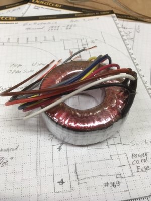
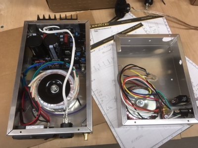
Update! I got some parts in to facilitate ByteFrenzy's idea to change up the physical layout. The first is a smaller box that fits better in the wooden frame, and the second is a new transformer from Hammond that is about 2/3 the size, but the same VA rating:

Current design is on the left. Hopefully I can stuff it all into the one on the right!

Current design is on the left. Hopefully I can stuff it all into the one on the right!
Attachments
mayfly
Epic Member
- Messages
- 9,175
Hi Folks,
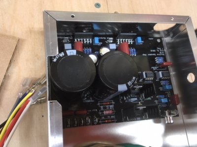
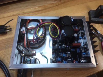
Been awhile, but managed to get back at this today. Unfortunately it's a good news / bad news situation. The good news is that I managed to squeeze the amp into a smaller package! Here it is:

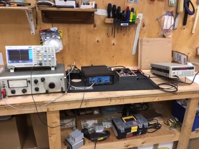
The bad news is that the performance of the amp sucks. I put together a THD rig to test it out, including my new-to-me HP distortion analyzer. Yes, that's a sholtz power soak as the dummy load.

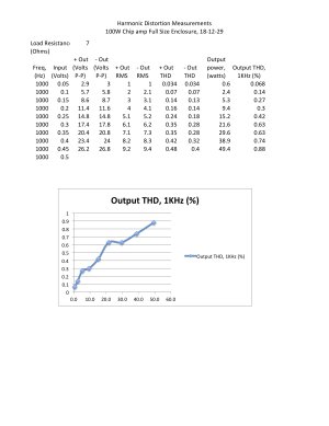
The results basically suck. THD runs almost up to 1%!! and it starts clipping at 50W. WTF??

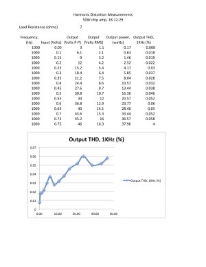
This really annoys me because I built a non-bridged version of the amp previously as a test, and it generated excellent results:

I need to figure out what's going on, but I suspect that I'm running into the thermal limits of the chip. That is, I suspect my heatsinks are too wimpy. Back to the drawing board (again).
Been awhile, but managed to get back at this today. Unfortunately it's a good news / bad news situation. The good news is that I managed to squeeze the amp into a smaller package! Here it is:
The bad news is that the performance of the amp sucks. I put together a THD rig to test it out, including my new-to-me HP distortion analyzer. Yes, that's a sholtz power soak as the dummy load.
The results basically suck. THD runs almost up to 1%!! and it starts clipping at 50W. WTF??
This really annoys me because I built a non-bridged version of the amp previously as a test, and it generated excellent results:
I need to figure out what's going on, but I suspect that I'm running into the thermal limits of the chip. That is, I suspect my heatsinks are too wimpy. Back to the drawing board (again).
Attachments
DarkPenguin
Senior Member
- Messages
- 370
Water cool it. For effect the water should pour down the inside of the speaker.
mayfly
Epic Member
- Messages
- 9,175
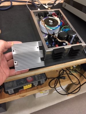
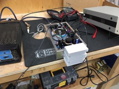
OK! I think I've gotten to the bottom of things. And no, it was not the heatsink. But I probably should do some thermal calculations in the future.
Anyway, here's the amp with the new heatsink. Some quality time with the drill press and a 6-32 tap and it's on tightly.

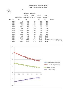
I didn't bother with THD measurements as I figured I should check out the lack of power first. I ran it up and wouldn't you know it the unit clipped at the same point. Thinking of occam's razor, I figured that the most likely culprit is the power supply. So I hooked up some probes thinking I'd get a bit but not a lot of sag. Well, Here's what I measured.

Yup. the +/- rails sag to around 50%. This alone should not cause clipping, but when you consider that my small signal power regulators run off of this supply, you start getting a little concerned. I've got good old 7815 / 7915 linear regulators which work great in their limits. Unfortunately one of those limits is that you've got to provide more voltage on the input than the regulated output voltage. About 2volts more according to the 7915 data sheet. Another measurement confirmed my thoughts: with the main rails collapsing, there was no longer enough voltage to run the regulators, with the negative rail giving up first. No negative rail makes the op-amps pretty unhappy. Yes - the clipping was in the op amps!
Found it.
Now - what the heck should I do about it? Probably I need to check my VA calculations for the power transformer, but I gotta tell ya, a transformer with a larger VA rating is not going to fit in that small enclosure.
Stay tuned...
Anyway, here's the amp with the new heatsink. Some quality time with the drill press and a 6-32 tap and it's on tightly.
I didn't bother with THD measurements as I figured I should check out the lack of power first. I ran it up and wouldn't you know it the unit clipped at the same point. Thinking of occam's razor, I figured that the most likely culprit is the power supply. So I hooked up some probes thinking I'd get a bit but not a lot of sag. Well, Here's what I measured.
Yup. the +/- rails sag to around 50%. This alone should not cause clipping, but when you consider that my small signal power regulators run off of this supply, you start getting a little concerned. I've got good old 7815 / 7915 linear regulators which work great in their limits. Unfortunately one of those limits is that you've got to provide more voltage on the input than the regulated output voltage. About 2volts more according to the 7915 data sheet. Another measurement confirmed my thoughts: with the main rails collapsing, there was no longer enough voltage to run the regulators, with the negative rail giving up first. No negative rail makes the op-amps pretty unhappy. Yes - the clipping was in the op amps!
Found it.
Now - what the heck should I do about it? Probably I need to check my VA calculations for the power transformer, but I gotta tell ya, a transformer with a larger VA rating is not going to fit in that small enclosure.
Stay tuned...
Attachments
Similar threads
- Replies
- 6
- Views
- 633
- Replies
- 8
- Views
- 994


