7/8 S-Style in Black Cherry / Wenge Warhead

syscokid

Junior Member
Messages
78
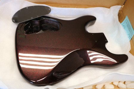
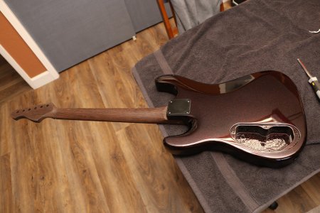
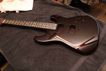
I was not expecting the Warmoth finished body with a Warmoth exotic wood neck to arrive until mid to late October. But, it was delivered last week, and assembly started a few days ago.

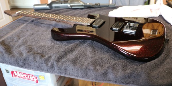
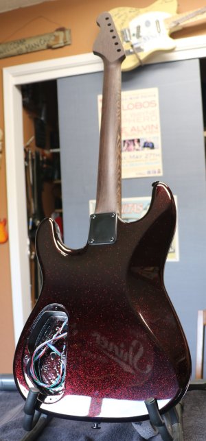
The body wood is roasted swamp ash covered in a beautiful and glossy metallic “black cherry” paint. So far it has been very hard to photographically capture the real beauty of this metallic paint.
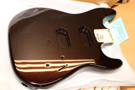
IMG_4142.JPG

IMG_4148.JPG

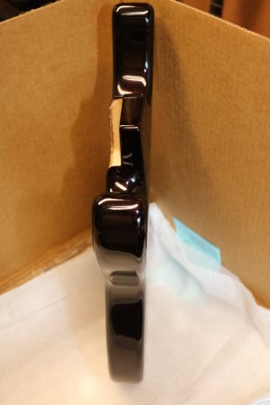
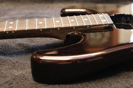
Contoured heel:
IMG_4150.JPG

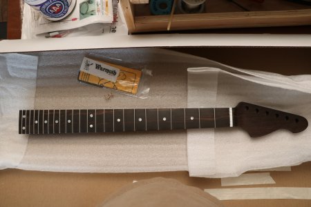
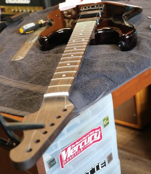
The neck wood is wenge. Fretboard is macassar ebony. 24 stainless steel 6105 frets (medium-jumbo, narrow). Mother of Pearl dot inlays. Moonglow side dots. Earvana corian nut.
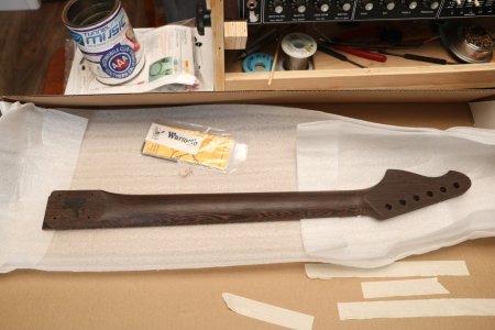
IMG_4135.JPG

IMG_4139.JPG

IMG_4173.JPG

IMG_4181.JPG

IMG_4193.JPG

When I went to install the Kluson tuners, I discovered an oddball bushing. Contacted Kluson (WD Music) and they are sending me a new package.
IMG_4198.JPG

The loose fitting bushing is on the right. IMO, it looks chewed or like it has been used before.
IMG_4206.JPG
 
What a great surprise, fantastic parts way earlier than expected! I honestly can't decide whether I like the body or neck more, they're both gorgeous. I really like the neck woods a lot. Can't wait to see how this turns out, enjoy the build!
 
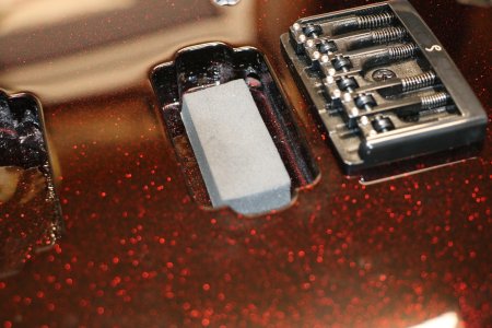
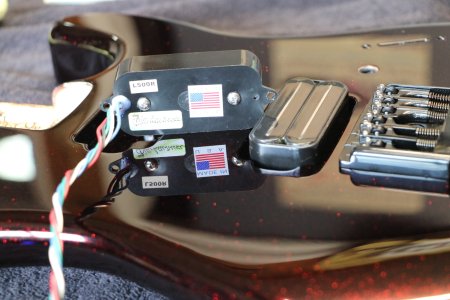
Moving on... Slowly... Today's progress involved strap buttons, Schaller 475 bridge, bridge ground wire, and a set of Bill And Becky Wilde Pickups (Bill Lawrence).
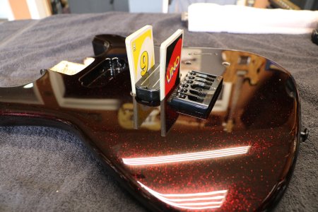
Found a neat trick at Youtube on centering the pickup with a deck of playing cards in preperation for wood mounting a pickup:
IMG_4207.JPG

IMG_4208.JPG

L500R (Rhythm) for the neck and L500L (Lead) for not the neck:IMG_4210.JPG

Won't see the new tuners for a few more days, so I went redneck! That's some 15 lb test, .015 monofilament that seems to be aligning up perfectly!
IMG_4211.JPG

So far, I really like the look of this:
IMG_4212.JPG

IMG_4213.JPG
 
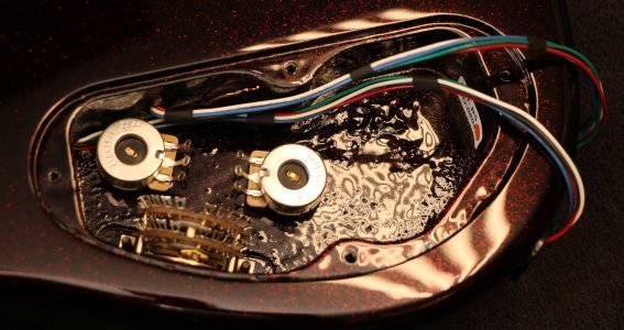
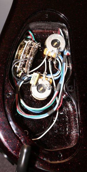
The latest: Pickup and control wiring!

IMG_4238.JPG


What does this sticker code mean?
IMG_4239.JPG


First time setting up a 4 pole 5-way superswitch:
IMG_4241.JPG


What I'm shooting for in the 5 pickup selections:
Position 1: Bridge in series
P 2: Bridge & neck outside coils in parallel
P 3: Bridge & neck in parallel
P 4: Bridge & neck inside coils in parallel
P 5: Neck in series

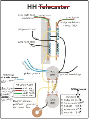
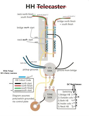
If positions 2 & 4 sound too redundant, I'll look into an alternative for one of those positions. I'm struggling hard to understand how these superswitches work. So, I used one of these diagrams with the same type of settings that I'm looking for:
HH Telecaster Wiring Diagram.jpg
I adjusted the wiring color scheme to match the Wilde pickups. Judging by the DC Resistance readings, it looks like it's working right.

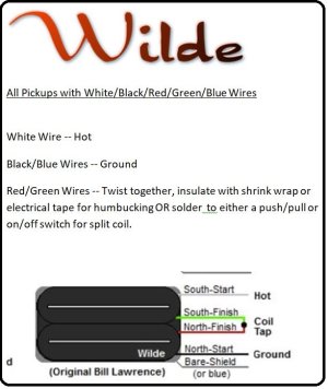
I used the following info for which wire is which:
Wilde Technical Pickup Info.JPG


I hope I did it right. Won't know for sure until I receive the new tuners... string it up... and wank away!
 
I hope I did it right. Won't know for sure until I receive the new tuners...

Or until given some help.

I adjusted the wiring color scheme to match the Wilde pickups. Judging by the DC Resistance readings, it looks like it's working right.

From the diagram, you have annotated the different colours incorrectly.

It won't work as expected as you have for hot (white) going to ground and the black wire which should be going to ground for the pickups you have going to the selection switch instead of white.

Effectively swap the black and white around. Currently, your diagram and wiring has black and white the wrong way around for the Wilde pickups.

You might have DC resistance, but both pickups are wired out of phase.

Note: on the first diagram, the wire from the switch to the pot and labelled ground from the bridge coloured black is wired correctly. However, this wire has nothing to do with the colour code of the pickups and serves an entirely different function. The original diagram might have been better to use a different colour for a ground wire in this case.
 
Last edited:
Fix the diagram and I will confirm if it is correct first to save you having to resolder more than once.
 
Or until given some help.
Thanks!

From the diagram, you have annotated the different colours incorrectly.
Now I’m really confused! The reason I decided to reverse the pickup’s black and white wires is because I see on diagram/2 that the pickup’s black wire is also labeled the North-Start of the coil, as it’s also labeled Ground. The pickup’s white wire is labeled South-Start, also labeled Hot. At diagram/1, I see the North-Start wire, which is black for the Wilde pickup, not used as a main ground. I see the neck’s North-Start black wire connected to positions 2 - 5 to the bottom left pole, and the bridge’s North-Start black wire is connected to positions 1 - 4 to the bottom right pole.

The pickup’s “Hot” white wire is labeled
South-Start. There’s no connection of the South-Start wire to the superswitch. I assumed the white South-Start wire now shares the ground with the Blue wire that always goes to ground.
 
That's some beautiful paint, and if it's anything like the clear that Warmoth put on my walnut body, no reasonable plastic pick will be able to scratch it.
 
Going with:

All Pickups with White/Black/Red/Green/Blue Wires

  • White Wire -- Hot
  • Black/Blue Wires -- Ground
  • Red/Green Wires -- Twist together, insulate with shrink wrap or electrical tape for humbucking OR solder to either a push/pull or on/off switch for split coil.
I have L500s and can confirm this is the correct wiring.

The wires on your adapted diagram now go to the correct places for that diagram. Where this diagram came from originally or its north-south annotations I cannot confirm but I can see why you mapped the wires the way you did originally but go with the reliable source cited above.

I assume you have a wire giving ground continuity between volume and tone, as the original diagram does not and assumes grounds via a control plate, which you do not have. From your photo of your control cavity it looks like you have and seems also confirmed by the DC resistance you have as it looks like your ground to the output jack is attached to the tone also.

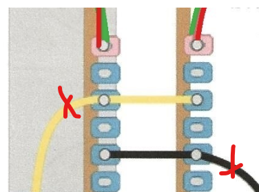
When you test, positions, 2 and 4 confirm whether the split coils are opposite (or not) to what is expected. If so, then all you need to do is swap the black and yellow wires. This is shown in the diagram extract below with two red x markings connecting to the superswitch leaving the jumpers across the poles in place.

wire swap.png


You can also test without strings by plugging into an amp (not too loud) and using a screwdriver or similar to tap on the pickups whilst testing the switching, volume and tone work as expected.

If there is something about the super switch you have a question about, I can answer it for you.
 
Last edited:
I assume you have a wire giving ground continuity between volume and tone…
Yes. There’s a ground wire from the vol pot to the tone pot, and another ground wire from tone to the sleeve of the output jack.

If there is something about the super switch you have a question about, I can answer it for you.
Awesome… 🍻 All the info that you have supplied me, at this thread or any other, has been spot on!

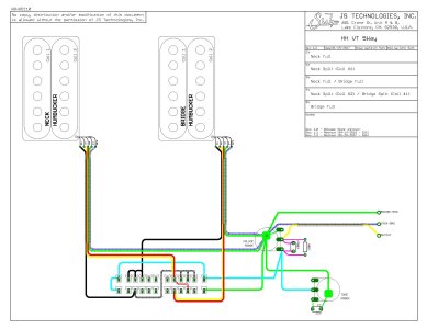
A couple days ago I found another H-H diagram that is very clear and shows me the connections that I think I’m going to like the most. Position 2 will produce inside coils in parallel, and position 4 produces a split-neck pickup with the outer coil being tapped:
IMG_0888.jpeg
In a perfect world, I rather have the P-4 neck-split into a neck pup in parallel instead. Can this be done without extra switching components?
 
In a perfect world, I rather have the P-4 neck-split into a neck pup in parallel instead. Can this be done without extra switching components?

When referring to the Suhr diagram for P-4 do you mean what the diagram in the table has marked as 2) Neck Split (Coil #1)?
 
Back
Top