

You are using an out of date browser. It may not display this or other websites correctly.
You should upgrade or use an alternative browser.
You should upgrade or use an alternative browser.
The Mystical Mahogany Build...
- Thread starter stratamania
- Start date
stratamania
Mythical Status
- Messages
- 12,399
Thanks, welcome to the forum.
I am only doing Tru Oil on the neck on this build. The body is already finished. Your 7/8 Tele build sounds good.
I am only doing Tru Oil on the neck on this build. The body is already finished. Your 7/8 Tele build sounds good.
stratamania
Mythical Status
- Messages
- 12,399
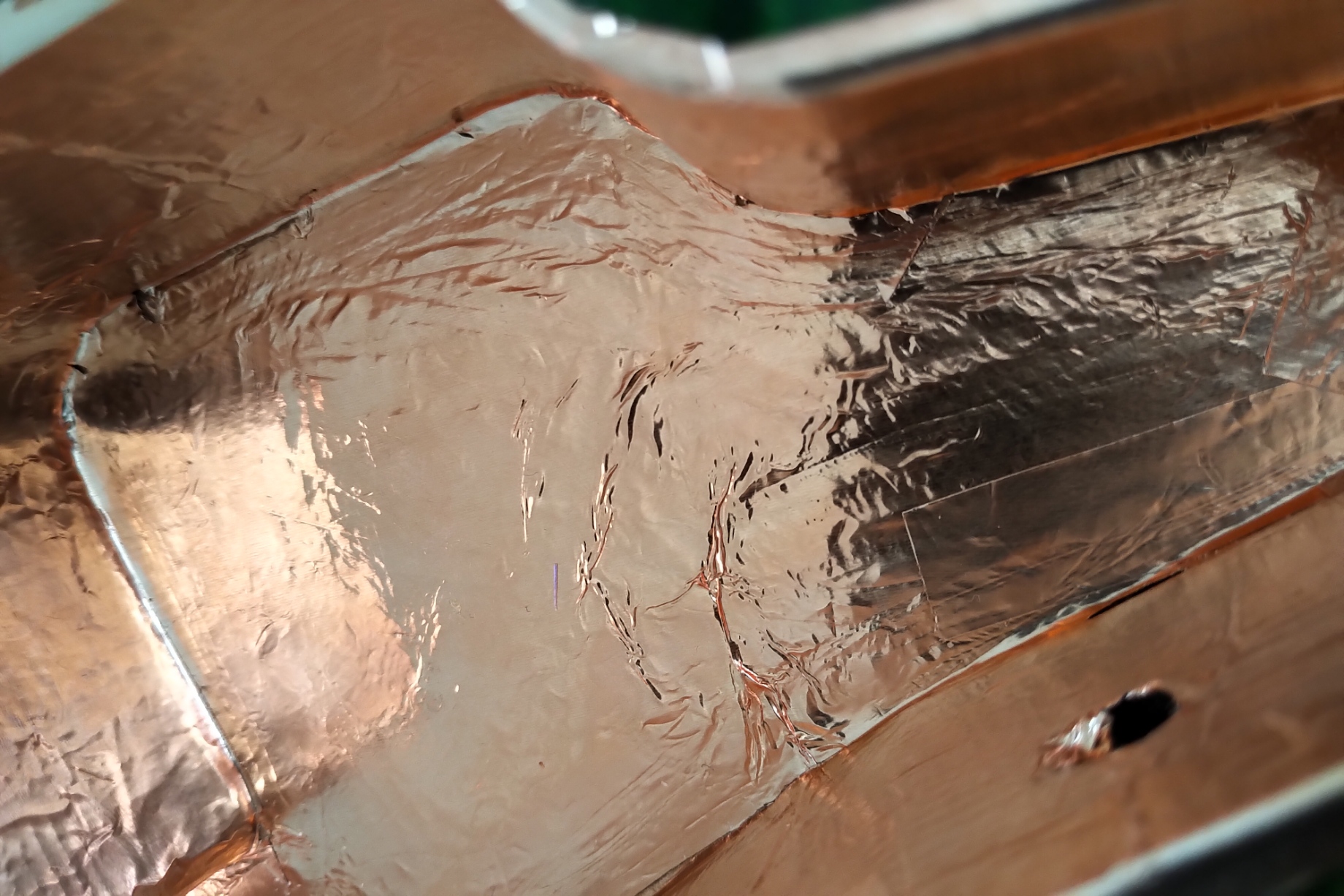
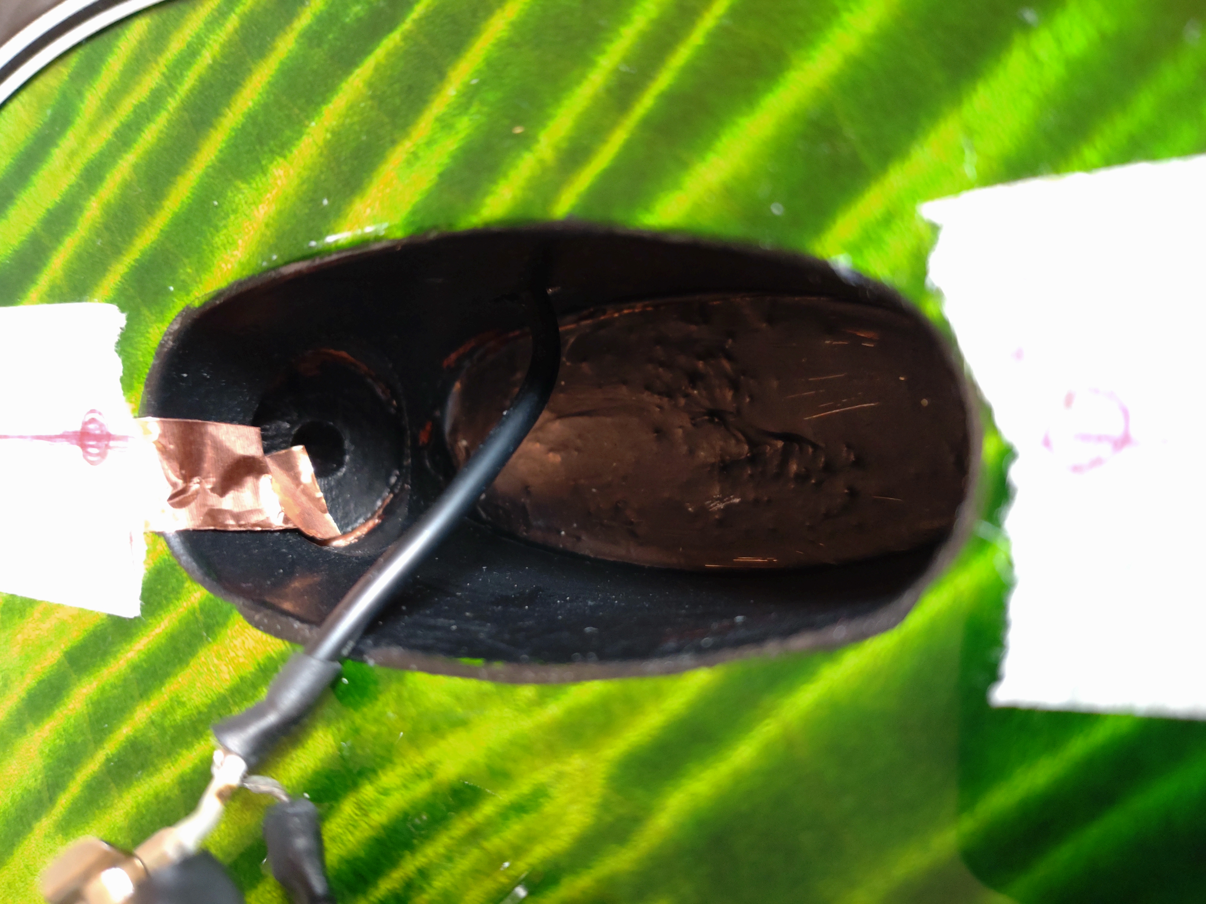
A short update. I spent some time today and shielded the body top rout cavity with copper foil and in the jack recess with conductive paint.
 shield by stratamania, on Flickr
I also have a new middle pickup so I can get to wiring at some point after diagramming out what I am going to do.
shield by stratamania, on FlickrI also have a new middle pickup so I can get to wiring at some point after diagramming out what I am going to do.
SeattleScotty
Senior Member
- Messages
- 215
That neck is just beautiful, I love the dark mahogany with the nice striped rosewood board. The mahogany looks especially rich and dark.
I just received the neck I ordered - walnut with a rosewood board. I have always thought a nice striped piece of rosewood always looked better than a plain ebony board.
I just received the neck I ordered - walnut with a rosewood board. I have always thought a nice striped piece of rosewood always looked better than a plain ebony board.
stratamania
Mythical Status
- Messages
- 12,399
@SeaGroomer I just saw your comment. Thanks for the feedback and glad you like the neck.
So not much progress on this build for a while. Anyway should be moving forward with it some more now.
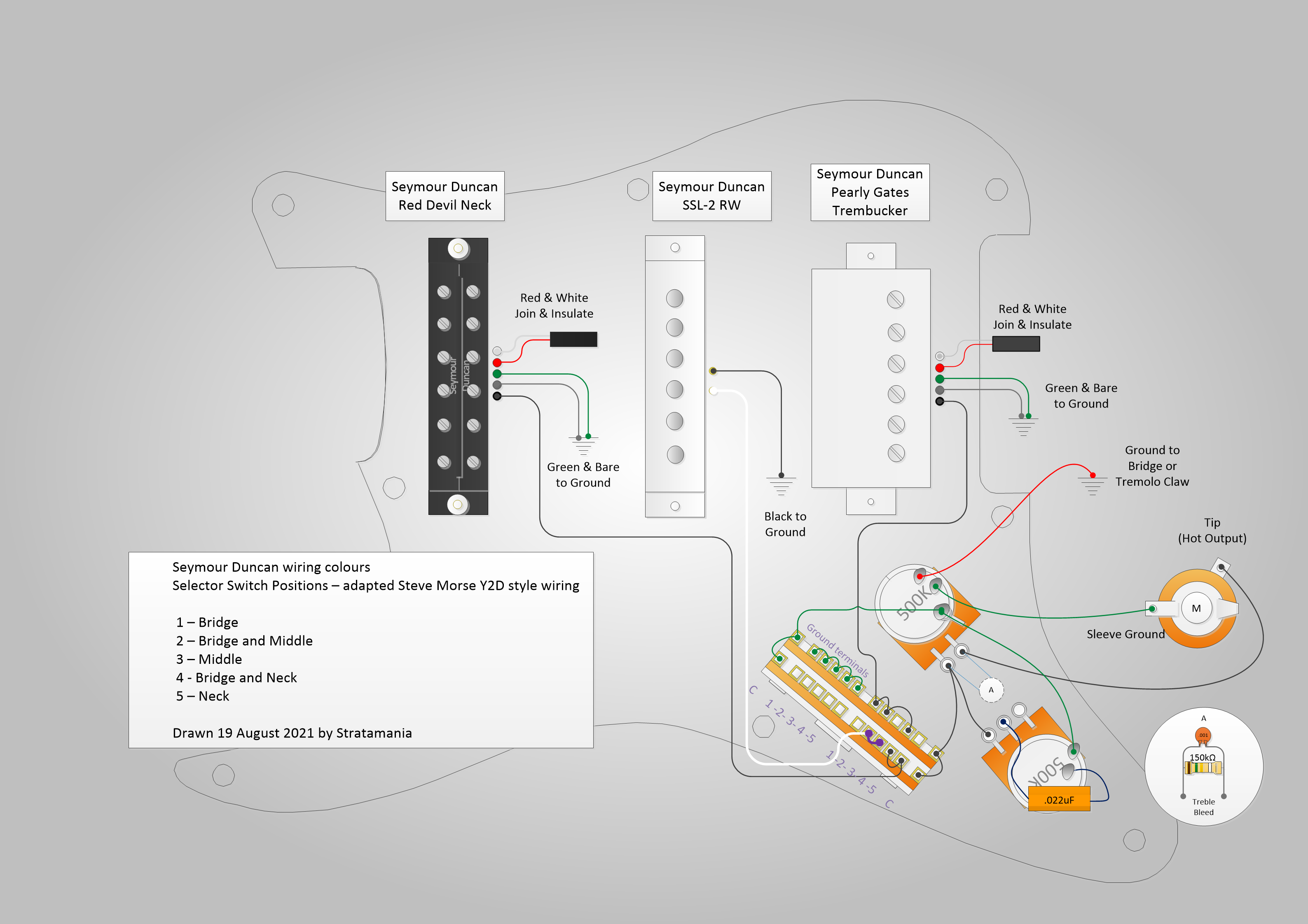
With the wiring in mind I made a diagram similar to the Steve Morse Y2D wiring but with 500K pots and different pickups etc.
I actually wanted a straightforward scheme with just 5 positions and so this is what I am going with.
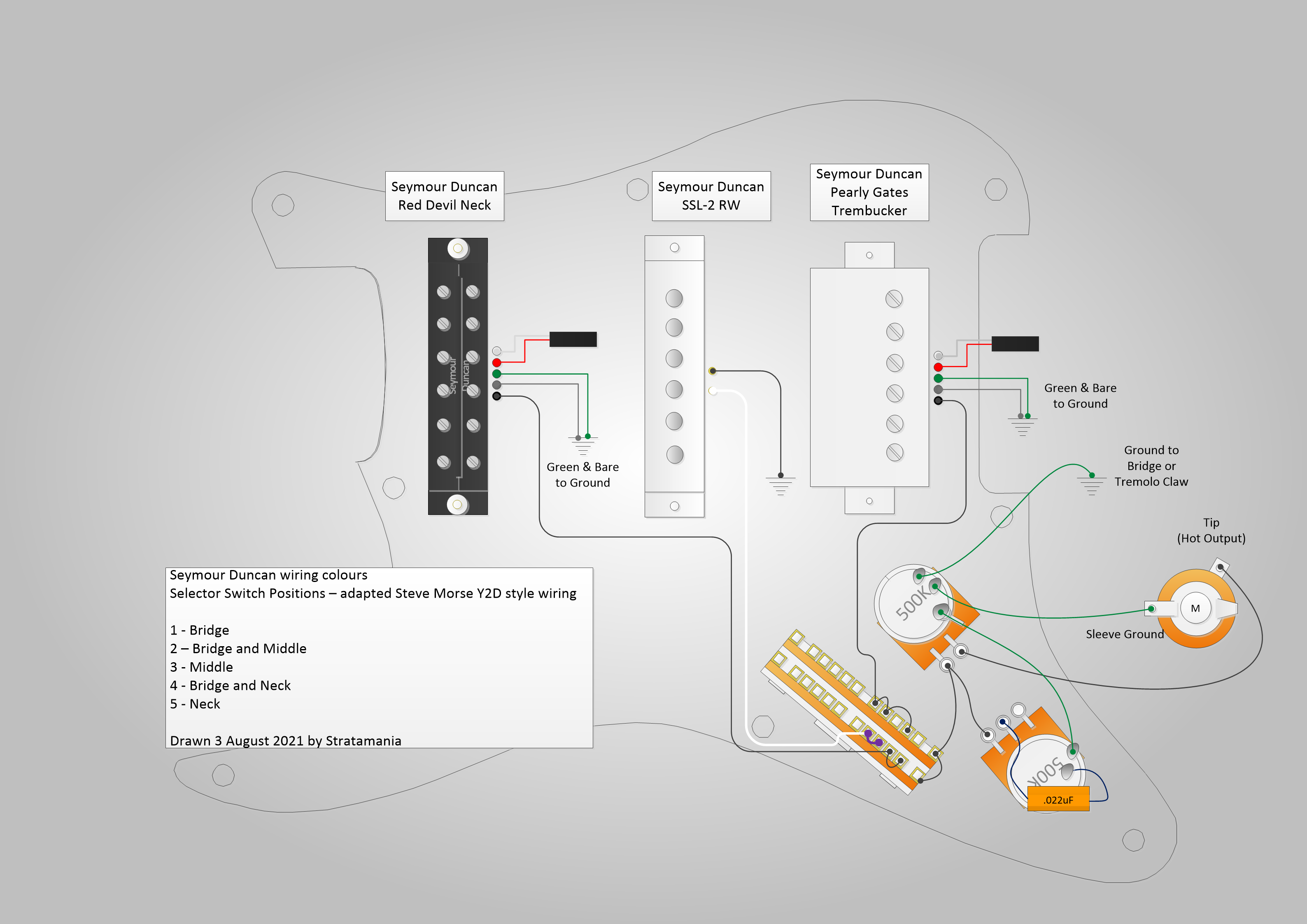 SteveMorseStyleWiring by stratamania, on Flickr
So not much progress on this build for a while. Anyway should be moving forward with it some more now.
With the wiring in mind I made a diagram similar to the Steve Morse Y2D wiring but with 500K pots and different pickups etc.
I actually wanted a straightforward scheme with just 5 positions and so this is what I am going with.
SteveMorseStyleWiring by stratamania, on Flickrstratamania
Mythical Status
- Messages
- 12,399
Well I woke up this morning - no really and it struck me that diagram is missing a couple of things. Will need to adjust it and post the new version.
stratamania
Mythical Status
- Messages
- 12,399
Without further ado... an update with the treble bleed shown and a couple of minor tweaks.
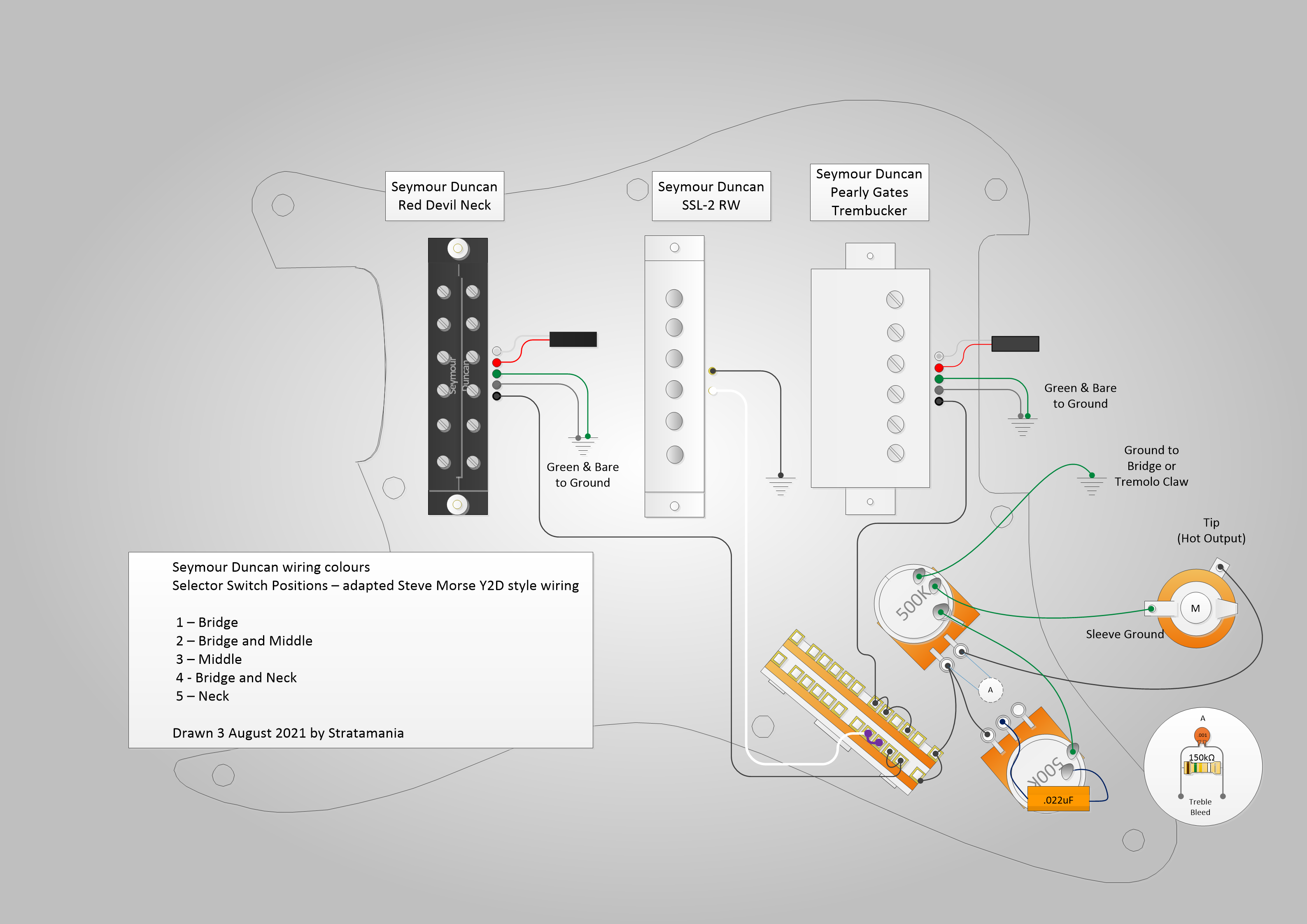 WiringUpdate by stratamania, on Flickr
WiringUpdate by stratamania, on FlickrDangerousR6
Mythical Status
- Messages
- 15,478
Very cool and tedious, but I think the neck looks better with tru oil... :icon_thumright:
stratamania
Mythical Status
- Messages
- 12,399
DangerousR6 said:Very cool and tedious, but I think the neck looks better with tru oil... :icon_thumright:
Thanks. I agree.
")
stratamania
Mythical Status
- Messages
- 12,399
SeattleScotty
Senior Member
- Messages
- 215
Are those active pickups? Is that the little black boxes with red wire going to the pickups? I see the treble bleed is going into the top pot, is that a volume pot and it drains the treble more when you lower the volume? I only see two knobs, so one tone and one volume?
I still don't really understand how tone knobs work lol. I get the orange cap is supposed to do something, but it looks like it's just sitting between the pot and the ground, so I dunno how that works lol. Also, is that big breadboard-looking thing commonly used? I can't say I've seen something like that, but I've only opened up a couple of guitars. :icon_scratch:
It's a good thing I sent mine out to have the electronics done by someone who knows what they're doing. :laughing3:
stratamania
Mythical Status
- Messages
- 12,399
A few things to answer here so I have unpacked it to separate things out.
No they are passive. the pickup types are mentioned above each pickup - remember it is a diagram and each symbol is not meant to be totally exact like a photo.
(I have active pickups in other guitars by the way)
The red and white wires are going to a black rectangle - it represents that the series link wires of each humbucker are joined together and the black symbol you could think of as the join with shrink wrap or insulation.
It has a master volume and master tone.
The treble bleed (sometimes called a volume kit) is on the volume pot. As a volume pot is lowered the tone will also darken to a degree.
What the treble bleed circuit does is provide an alternative path bypassing the pot for the treble to bleed through so as the volume is rolled off you do not lose any treble.
A cap will filter the highs to ground - on a tone pot as you roll it off the tone loses highs or treble and thus sounds bassier or duller. The more you turn the pot down the more treble is filtered.
The treble bleed on the volume knob and the tone knob are effectively doing opposite tasks - allowing treble to pass or to filter it away.
https://www.stewmac.com/video-and-ideas/online-resources/learn-about-guitar-pickups-and-electronics-and-wiring/how-a-tone-control-works/
I think you must be looking at the part of the diagram that represent a super switch, which is a 5 way switch with four poles. There are 24 terminals that can be soldered to...so a good idea to know which one is which
Like any job if you don't have the tools or are not sure of something it makes sense to get help.
But this stuff can be learnt...you just need to start with the basics and go from there.
A good place to start is here.
https://www.seymourduncan.com/blog/latest-updates/guitar-wiring-diploma-course
I should be doing the actual wiring soon so watch this space as I will try and get more photos to post etc.
SeaGroomer said:Are those active pickups?
No they are passive. the pickup types are mentioned above each pickup - remember it is a diagram and each symbol is not meant to be totally exact like a photo.
(I have active pickups in other guitars by the way)
SeaGroomer said:Is that the little black boxes with red wire going to the pickups?
The red and white wires are going to a black rectangle - it represents that the series link wires of each humbucker are joined together and the black symbol you could think of as the join with shrink wrap or insulation.
SeaGroomer said:I see the treble bleed is going into the top pot, is that a volume pot and it drains the treble more when you lower the volume? I only see two knobs, so one tone and one volume?
It has a master volume and master tone.
The treble bleed (sometimes called a volume kit) is on the volume pot. As a volume pot is lowered the tone will also darken to a degree.
What the treble bleed circuit does is provide an alternative path bypassing the pot for the treble to bleed through so as the volume is rolled off you do not lose any treble.
SeaGroomer said:I still don't really understand how tone knobs work lol. I get the orange cap is supposed to do something, but it looks like it's just sitting between the pot and the ground, so I dunno how that works lol.
A cap will filter the highs to ground - on a tone pot as you roll it off the tone loses highs or treble and thus sounds bassier or duller. The more you turn the pot down the more treble is filtered.
The treble bleed on the volume knob and the tone knob are effectively doing opposite tasks - allowing treble to pass or to filter it away.
https://www.stewmac.com/video-and-ideas/online-resources/learn-about-guitar-pickups-and-electronics-and-wiring/how-a-tone-control-works/
SeaGroomer said:Also, is that big breadboard-looking thing commonly used? I can't say I've seen something like that, but I've only opened up a couple of guitars. :icon_scratch:
I think you must be looking at the part of the diagram that represent a super switch, which is a 5 way switch with four poles. There are 24 terminals that can be soldered to...so a good idea to know which one is which
SeaGroomer said:It's a good thing I sent mine out to have the electronics done by someone who knows what they're doing. :laughing3:
Like any job if you don't have the tools or are not sure of something it makes sense to get help.
But this stuff can be learnt...you just need to start with the basics and go from there.
A good place to start is here.
https://www.seymourduncan.com/blog/latest-updates/guitar-wiring-diploma-course
I should be doing the actual wiring soon so watch this space as I will try and get more photos to post etc.
stratamania
Mythical Status
- Messages
- 12,399
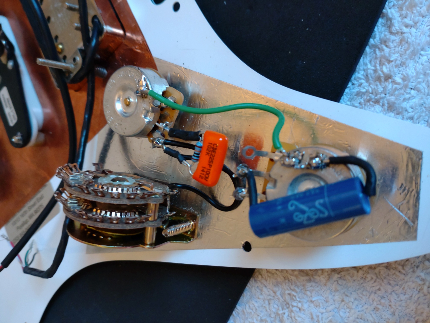
I broke out some soldering tools today and set myself up a space to work where I can leave things out till I have this part of the job finished.
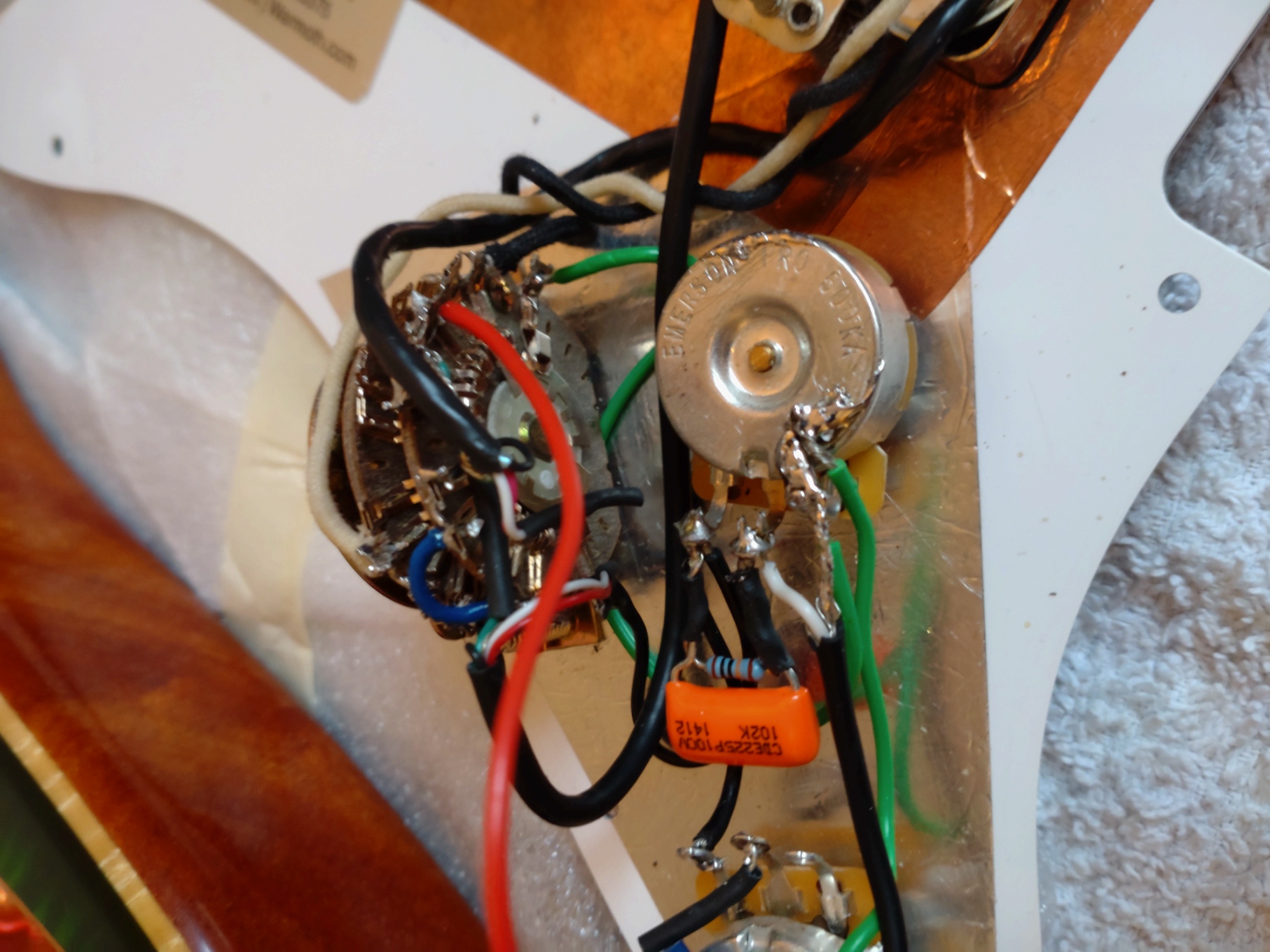
The tone pot is done and the common hot from the selector switch to the volume. The hot from the volume pot to the tone pot is also complete.
The treble bleed cap and resistor circuit is done though the connection to the middle lug is only in place and will be soldered when I do the output to the jack.
By the way a ceramic cap works just as well for a treble bleed circuit but I had this orange one in amongst the parts. And the SoZo cap is not essential either on the tone pot - as long as there is a cap with the correct value it will do.
 wiring (2) by stratamania, on Flickr
This is not my best soldering though it should be functional. I can see this photo okay but I am struggling a bit with vision at the moment for close up things at times, so am having to rely on either magnification or my Opti-visor.
Should be more to follow tomorrow.
The tone pot is done and the common hot from the selector switch to the volume. The hot from the volume pot to the tone pot is also complete.
The treble bleed cap and resistor circuit is done though the connection to the middle lug is only in place and will be soldered when I do the output to the jack.
By the way a ceramic cap works just as well for a treble bleed circuit but I had this orange one in amongst the parts. And the SoZo cap is not essential either on the tone pot - as long as there is a cap with the correct value it will do.
wiring (2) by stratamania, on FlickrThis is not my best soldering though it should be functional. I can see this photo okay but I am struggling a bit with vision at the moment for close up things at times, so am having to rely on either magnification or my Opti-visor.
Should be more to follow tomorrow.
SeattleScotty
Senior Member
- Messages
- 215
Awesome! Thanks for the explanation! That is pretty cool wiring. I saw on the seymour duncan website they have diagrams for like 100 different setups haha.
One thing I still don't understand is where the signal is going from the tone pot. It seems like the cap is just going to ground? I don't see where else it would be going.
One thing I still don't understand is where the signal is going from the tone pot. It seems like the cap is just going to ground? I don't see where else it would be going.
stratamania
Mythical Status
- Messages
- 12,399
SeaGroomer said:Awesome! Thanks for the explanation! That is pretty cool wiring. I saw on the seymour duncan website they have diagrams for like 100 different setups haha.
One thing I still don't understand is where the signal is going from the tone pot. It seems like the cap is just going to ground? I don't see where else it would be going.
Thanks.
On the SD website the link I posted for the wiring explanations were written by another forum member on here. He does not post on the forum so often these days but he has done a lot of good work on the SD site with tutorials and blog articles.
Correct the capacitor is just going to ground on the tone pot. The hot signal from the volume pot to the tone pot as you roll down the tone pot more high end goes to ground resulting in what a tone control does.
Also all pots or potentiometers do is they are variable resistors. On a volume pot as you turn down the pot more signal goes to ground resulting in a loss of volume.
stratamania
Mythical Status
- Messages
- 12,399
I got a bit more progress done today and as you all like pictures here are a couple more.
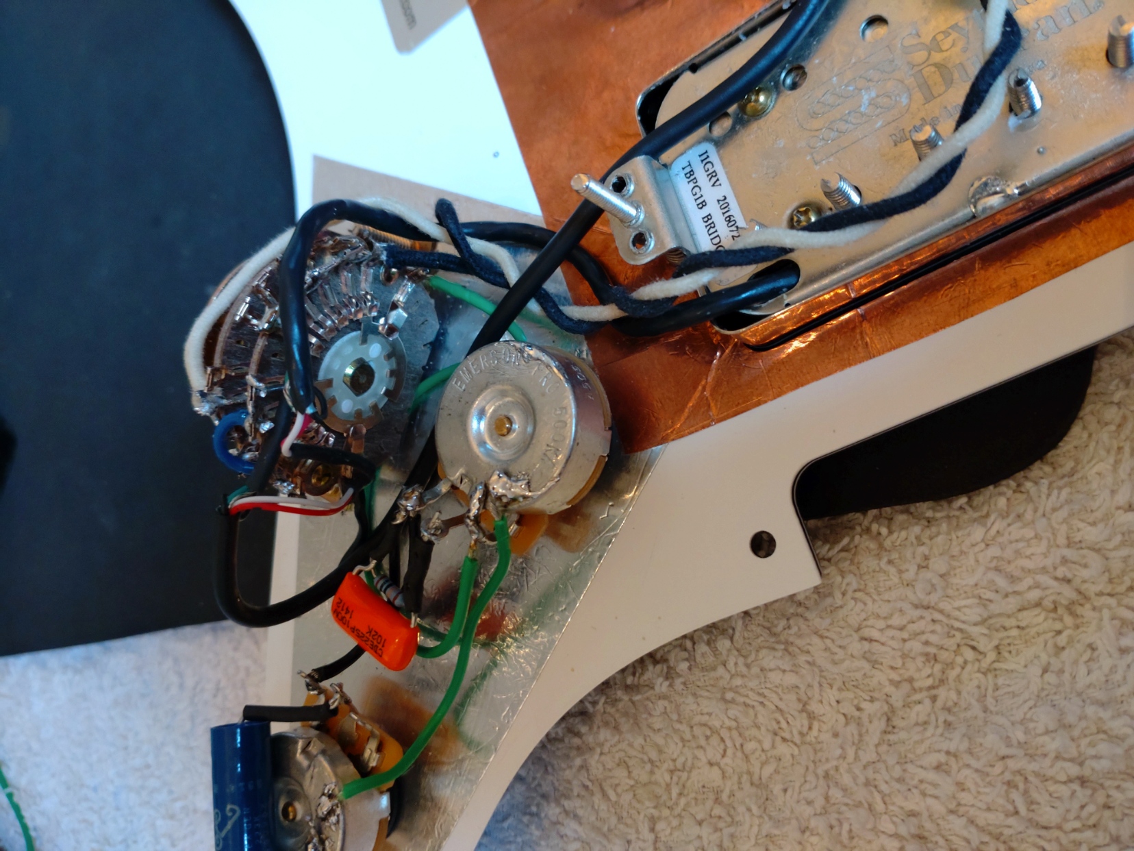
All the wiring complete as far as it can be for now and wiring adjusted to make sure the pickguard sits flush consistently in the body.
 wiring (3) by stratamania, on Flickr
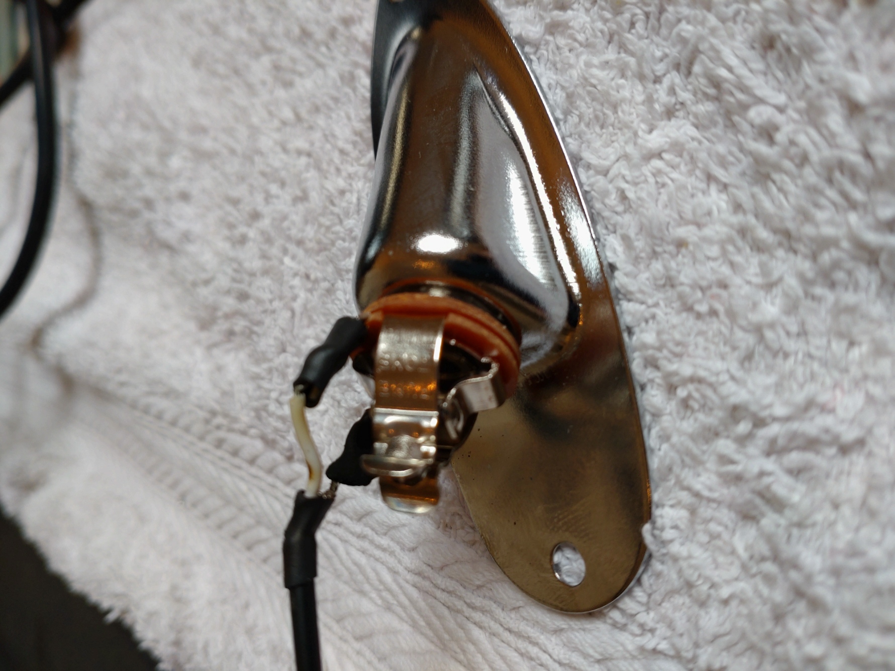
In preparation for the next steps the Puretone jack fitted to the jack plate and the output wire attached.
 wiring (4) by stratamania, on Flickr
Next will be fitting the trem claw with a ground wire, then fitting the jack, running the output wire to the control cavity and soldering it and the bridge ground wire to the controls - testing...
All the wiring complete as far as it can be for now and wiring adjusted to make sure the pickguard sits flush consistently in the body.
wiring (3) by stratamania, on FlickrIn preparation for the next steps the Puretone jack fitted to the jack plate and the output wire attached.
wiring (4) by stratamania, on FlickrNext will be fitting the trem claw with a ground wire, then fitting the jack, running the output wire to the control cavity and soldering it and the bridge ground wire to the controls - testing...
stratamania
Mythical Status
- Messages
- 12,399
I completed the wiring today and will post a couple of pics in the next post.
In the meantime here is an updated version of the wiring diagram. The pickup selections are as they were but the main changes are:
 WiringUpdate2 by stratamania, on Flickr
In the meantime here is an updated version of the wiring diagram. The pickup selections are as they were but the main changes are:
- Added numbering below selector switch to show common and terminal numbering
- Changed colour of ground wire to bridge or tremolo claw to red to match the actual wiring
- Added a common ground wire on the remaining two poles of the super switch to the volume pot ground
- Added jumper between all positions on one pole shown in green to act as ground terminals, which gives a continuous ground regardless of switch position. This was used to ground the pickups for example
WiringUpdate2 by stratamania, on Flickrstratamania
Mythical Status
- Messages
- 12,399
The Claw
First today was soldering a ground wire to the claw whilst outside of the body. Then the claw was screwed in and the wire fed to through to the control cavity. (screws lubricated with Behlens Slideez which is the white stuff showing on the screws)
 claw by stratamania, on Flickr
Wiring complete
As mentioned in the last updated diagram post prior to this one I added a common ground wire on the remaining two poles of the super switch to the volume pot ground and added a jumper between all positions on one pole shown in green to act as ground terminals, which gives a continuous ground regardless of switch position. I used part of a 10 gauge guitar string threaded through terminals 1 to 5 inclusive and soldered to achieve this. This gave me a set of terminals to ground the pickups and to add the red wire for the ground to the bridge. I used red as it is an obvious colour to distinguish this wire if I ever need to do maintenance. The red wire as can be seen in the photo below is connected to the grounding point on the super switch. I left the diagram showing this wire going to a grounding point on the volume pot for diagrammatic clarity.
The green and bare of the humbuckers are not really visible in the photo as I insulated them with heat shrink to avoid the bare wire inadvertently touching a positive terminal and creating a short.
The wire from the output jack was threaded through to the control cavity also and soldered to the relevant lugs of the volume pot.
 wiring_complete by stratamania, on Flickr
So now the wiring is complete does it work...
Dry fit and testing
I dry fitted the output jack and the loaded pickguard and plugged into an amp. Using a screwdriver I did a tap test and all positions work as they should as do the volume and tone as planned.
And here is a sneak peak of the dry fitted pieces and part of the body. (I am trying to keep you all updated but create some suspense along the way of how the whole thing will look
 fit_and_test by stratamania, on Flickr
As always thanks for looking and feel free to ask relevant questions etc.
First today was soldering a ground wire to the claw whilst outside of the body. Then the claw was screwed in and the wire fed to through to the control cavity. (screws lubricated with Behlens Slideez which is the white stuff showing on the screws)
claw by stratamania, on FlickrWiring complete
As mentioned in the last updated diagram post prior to this one I added a common ground wire on the remaining two poles of the super switch to the volume pot ground and added a jumper between all positions on one pole shown in green to act as ground terminals, which gives a continuous ground regardless of switch position. I used part of a 10 gauge guitar string threaded through terminals 1 to 5 inclusive and soldered to achieve this. This gave me a set of terminals to ground the pickups and to add the red wire for the ground to the bridge. I used red as it is an obvious colour to distinguish this wire if I ever need to do maintenance. The red wire as can be seen in the photo below is connected to the grounding point on the super switch. I left the diagram showing this wire going to a grounding point on the volume pot for diagrammatic clarity.
The green and bare of the humbuckers are not really visible in the photo as I insulated them with heat shrink to avoid the bare wire inadvertently touching a positive terminal and creating a short.
The wire from the output jack was threaded through to the control cavity also and soldered to the relevant lugs of the volume pot.
wiring_complete by stratamania, on FlickrSo now the wiring is complete does it work...
Dry fit and testing
I dry fitted the output jack and the loaded pickguard and plugged into an amp. Using a screwdriver I did a tap test and all positions work as they should as do the volume and tone as planned.
And here is a sneak peak of the dry fitted pieces and part of the body. (I am trying to keep you all updated but create some suspense along the way of how the whole thing will look
fit_and_test by stratamania, on FlickrAs always thanks for looking and feel free to ask relevant questions etc.
stratamania
Mythical Status
- Messages
- 12,399
A bit more body fitting today...
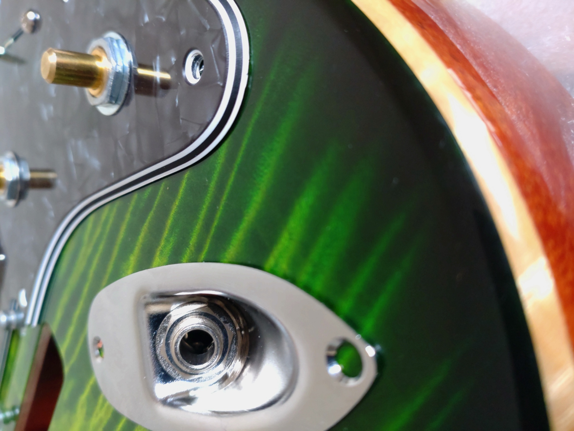
Using some masking tape to mark where I want the jack plate mounting screws to go. Before drilling the holes I plugged into an amp to do a tap test again to ensure all was working in that position. As all was good I then was able to drill the holes.
 BF (1) by stratamania, on Flickr
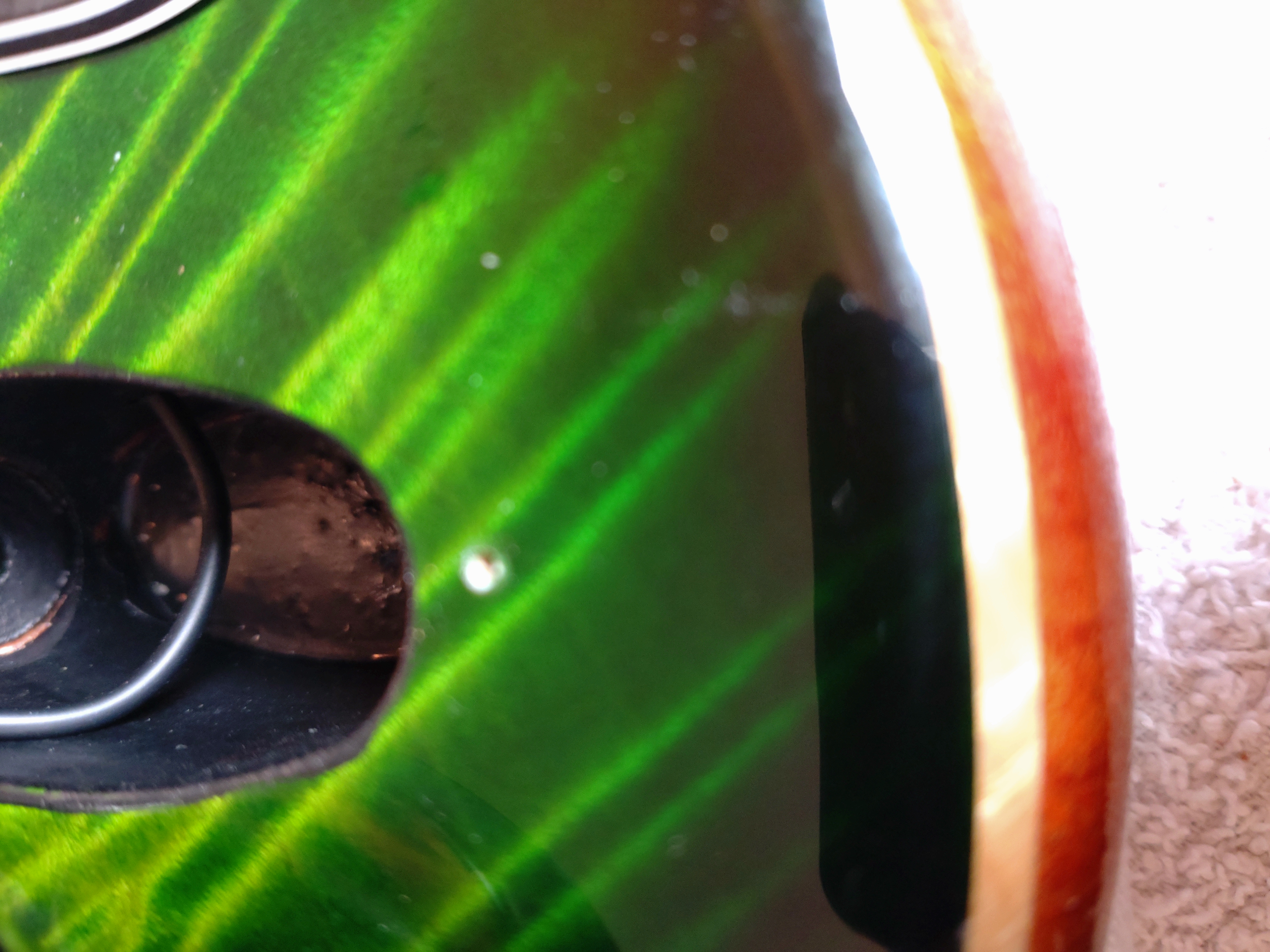
After drilling the initial holes through the masking tape with a 1.5mm bit I was able to remove the tape.
I then widen the top of the hole to 2mm but only about 3mm deep.
Note also the copper tape is there to make contact between the jack plate and the conductive paint in the jack recess. I also use shielded wire between jack and control cavities.
 BF (2) by stratamania, on Flickr
I then use a countersink bit just at the top of the hole to prevent finish popping.
 BF (3) by stratamania, on Flickr
After making sure any wood dust from the pilot holes is blown away it is then screwed into place.
 BF (4) by stratamania, on Flickr
I then repeat the tap test plugged into an amp to ensure all is working correctly. If a short occurs or something I want to know so I can correct it straight away.
Using some masking tape to mark where I want the jack plate mounting screws to go. Before drilling the holes I plugged into an amp to do a tap test again to ensure all was working in that position. As all was good I then was able to drill the holes.
BF (1) by stratamania, on FlickrAfter drilling the initial holes through the masking tape with a 1.5mm bit I was able to remove the tape.
I then widen the top of the hole to 2mm but only about 3mm deep.
Note also the copper tape is there to make contact between the jack plate and the conductive paint in the jack recess. I also use shielded wire between jack and control cavities.
BF (2) by stratamania, on FlickrI then use a countersink bit just at the top of the hole to prevent finish popping.
BF (3) by stratamania, on FlickrAfter making sure any wood dust from the pilot holes is blown away it is then screwed into place.
BF (4) by stratamania, on FlickrI then repeat the tap test plugged into an amp to ensure all is working correctly. If a short occurs or something I want to know so I can correct it straight away.
Similar threads
- Replies
- 1
- Views
- 120
- Replies
- 12
- Views
- 379