ChrisMC
Junior Member
- Messages
- 150
Hi everyone....the preparation part of this build that has been the most time consuming, by FAR, is TRYING to decide (key word there is trying...) how I'm going to wire my HH Soloist. I still haven't decided, and it's driving me crazy.
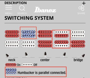
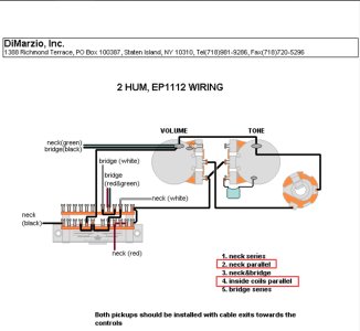
I did come across this diagram and this wiring option is in the running, but it doesn't tell me which coils are active when split. What I want (and won't settle for the opposite option) is the outer coils active when split (south coil on the bridge).
Does anyone know these Super Switch wiring diagrams well enough to know if that's the case, or if it's giving the inner coils with the splits?
These are, of course...Dimarzio wire color codes....red is hot.
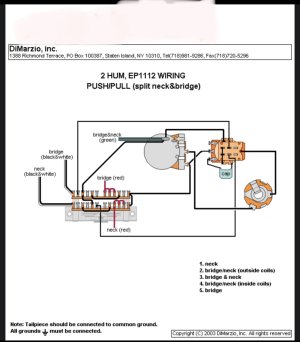
ALSO, for clarity - as far as I understand it (I've been looking at a lot of these on Dimarzio's site)...the 5 switch positions listed, are WITHOUT the DPDT push/pull engaged and splitting the coils. In other words, you still get those 5 positions when the push/pull is NOT engaged. Engaging the push/pull will split the bridge and neck, mostly useful for positions 1 and 5 on the switch in this case. If I'm wrong on that, and you ONLY get the splits on positions 2 and 4 WHEN the push/pull is engaged, then...I won't be using this wiring, as there are other similar Super Switch wiring options, that don't require the use of a DPDT to get you at least one of the two positions 2 or 4.
Thank you.
I did come across this diagram and this wiring option is in the running, but it doesn't tell me which coils are active when split. What I want (and won't settle for the opposite option) is the outer coils active when split (south coil on the bridge).
Does anyone know these Super Switch wiring diagrams well enough to know if that's the case, or if it's giving the inner coils with the splits?
These are, of course...Dimarzio wire color codes....red is hot.
ALSO, for clarity - as far as I understand it (I've been looking at a lot of these on Dimarzio's site)...the 5 switch positions listed, are WITHOUT the DPDT push/pull engaged and splitting the coils. In other words, you still get those 5 positions when the push/pull is NOT engaged. Engaging the push/pull will split the bridge and neck, mostly useful for positions 1 and 5 on the switch in this case. If I'm wrong on that, and you ONLY get the splits on positions 2 and 4 WHEN the push/pull is engaged, then...I won't be using this wiring, as there are other similar Super Switch wiring options, that don't require the use of a DPDT to get you at least one of the two positions 2 or 4.
Thank you.
 ccasion14: