Leaderboard

Vintage Tele Build - Control Plate Issues

Ozopart

Senior Member
Messages
262
I purchased Fralin Blues Special Neck and Bridge pickups and installed them in the pickguard and bridge. So far no issues there. I tested them after installation with my multimeter and they read fine.
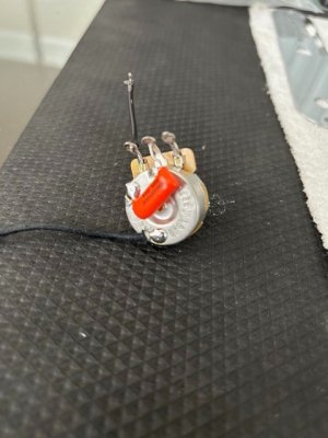
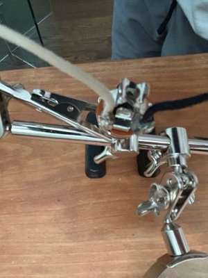
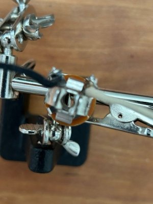
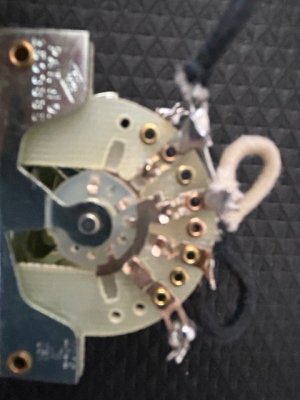
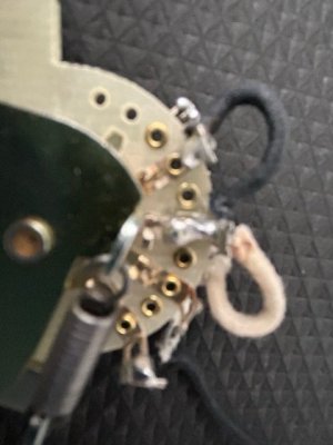
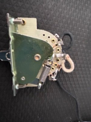
I build a control plate with a 3 way switch. It isn't elegant but seems to have continuity. I messed up there as online advice said to use Weller ETB tips with my Weller 1010NA soldering station. I had lots of trouble getting the solder to flow (60/40 solder) and as a result the connections look messy. But they seem to have continuity based on my multimeter.
I connected everything, put strings on the guitar (probably should have only put one on to test, but ...) and plugged it in. I got sound for a second and then nothing.
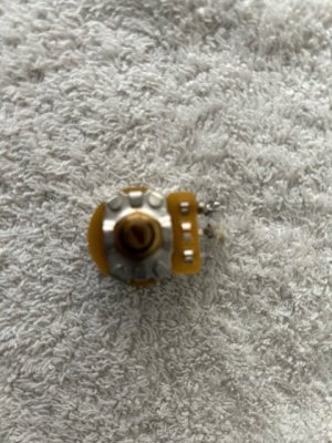
I disconned the control plate and re-tested the wiring. Everything test OK but the volume pot seems dead.

A couple of questions:
(1) Would my problems with solder not flowing, and as a result having to set the solder station tem higher (750F), be possibly due to the pointed tip rather than a chisel tip. I used the ETB tip but it looks like maybe the ETD chisel tip would have been better.
(2) If I fried the volume pot because I had to hold the tip at 750 F for longer than desired have caused the pot to pass sound for a second than go dead, could this be the only issue and mean I just need a new volume pot?

Finally, any suggestions other than Amazon ( I looked there and couldn't find the tip), for where to find the Weller ETD tip? I am wondering if that station is a good choice as finding tips seems to be really hard.

Thanks!
 
Weller tips

See below link where to buy online and dealer locator.


It's quite possible you have either fried the pot, have cold solder joints, shorts etc. As we cannot see a photo of the work, it could be any of these things.

You don't need strings to test wiring, you can tap the pickups with a metal object such as a screwdriver to get sound.
 
I’m unsure how easy it is to kill the volume pot. Can test the circuit with resistance meter? For example, disconnect the cable from the amp and measure the resistance between the inner and outer of the 1/4" plug. You should get: 1) When volume control is set to 50%, it should measure roughly 55k to 70k, 2) Volume at minimum, it should be less than 1k , 3) At full volume you are just measureing the resistance of the pickups, ie. around 7k or 8k typically

I don't see a problem with having a hot soldering iron. 750 degrees is probably the minimum I would use. In my opinion its ok to use a hotter iron. The trick is to apply the iron for only shortest period of time needed to do the job. The potential problem caused by a hot iron is you end up with more contimination and carbon on the soldering iron. To avoid having a lot of contamination you should continually wipe the tip of the iron on a damp sponge or a damp cloth, then apply fresh solder every time you make a connection.
 
Last edited:
I’m unsure how easy it is to kill the volume pot. Can test the circuit with resistance meter? For example, disconnect the cable from the amp and measure the resistance between the inner and outer of the 1/4" plug. You should get: 1) When volume control is set to 50%, it should measure roughly 55k to 70k, 2) Volume at minimum, it should be less than 1k , 3) At full volume you are just measureing the resistance of the pickups, ie. around 7k or 8k typically

I don't see a problem with having a hot soldering iron. 750 degrees is probably the minimum I would use. In my opinion its ok to use a hotter iron. The trick is to apply the iron for only shortest period of time needed to do the job. The potential problem caused by a hot iron is you end up with more contimination and carbon on the soldering iron. To avoid having a lot of contamination you should continually wipe the tip of the iron on a damp sponge or a damp cloth, then apply fresh solder every time you make a connection.
Thanks. I do believe that the volume pot is not working properly. With the multimeter I can get readings touching the middle lug and one of the other lugs. But one of the other lugs (not the middle) looks dull grey and doesn't register any reading. I think that is what got fried. I had my son-in-law helping me and he couldn't get solder to pool and "dry" on the pot and I am certain he ended up holding the pointed tip on the back of the pot for waaaay to long.
Going forward I am going to do this myself and just try to learn and improve on my soldering skills (or currently, my lack of soldering skills!).
I ordered 3 Weller ETD tips which are chisel tips and seem to be the right size. I think that will help. I will practice on some old parts first but I think the pointed tip was a problem in heat transfer. I just had to hold the tip on things way to long.
I do continually wipe the iron tip on the damp sponge and I also have that bronze looking tool with steel wool stuff inside of it that I use to clean off the tip with.
 
Weller tips

See below link where to buy online and dealer locator.


It's quite possible you have either fried the pot, have cold solder joints, shorts etc. As we cannot see a photo of the work, it could be any of these things.

You don't need strings to test wiring, you can tap the pickups with a metal object such as a screwdriver to get sound.
Thanks, as note above in reply to JohnnyHardtail, I ordered 3 ETD tips this morning. I do think the pot is compromised, but I wouldn't doubt if I have cold solder joints. Not sure how to determine if there is a short or not. Either way, I am going to consider this a failed attempt and start over. I have a 4 way switch on hand and the neck pickup I ordered from Fralin has the 3 wires. So I am thinking of attempting to do the 4 way wiring scheme.
On the strings, I should have known that. Thanks for reminding me. I think I can leave them on as the pickups are properly installed, and I have a ground wire under the bridge. I will just need to ground it to a pot when I build the control plate out.
 
This is why I never solder to the bottom of a pot. They were never designed for it. I use a common ground point for all grounds. Every ground connection has a wire to this central point. Its those 2 posts circled in black. They also ground the copper tape by being screwed on to it.

IMG_2025-09-02-081832.jpeg

IMG_2025-09-02-081345.jpeg
 
Is the control cavity lined with copper foil?

If so, it could be that when you check continuity with the control plate out of the body everything works fine, but when you install the control plate something makes contact with the copper foil and grounds out the signal.

I've had this happen before several times, particularly with 1/4" jacks.

It always feels just like this:

 
Last edited:
Is the control cavity lined with copper foil?

If so, it could be that when you check continuity with the control plate out of the body everything works fine, but when you install the control plate something makes contact with the copper foil and grounds out the signal.

I've had this happen before several times, particularly with 1/4" jacks.

It always feels just like this:

Nope, just wood as delivered by Warmoth. I really think the volume pot is fried.
 
This is why I never solder to the bottom of a pot. They were never designed for it. I use a common ground point for all grounds. Every ground connection has a wire to this central point. Its those 2 posts circled in black. They also ground the copper tape by being screwed on to it.

View attachment 66342

View attachment 66343
Interesting. Three questions: (1) Where do you get the plate/posts that you are using to ground to? (2) Am I correct that to connect the ground wires to the posts you solder them, or do you screw them in? (3) For the plate/posts, you just drill a hole in the side of the cavity and screw it in?
 
Interesting. Three questions: (1) Where do you get the plate/posts that you are using to ground to? (2) Am I correct that to connect the ground wires to the posts you solder them, or do you screw them in? (3) For the plate/posts, you just drill a hole in the side of the cavity and screw it in?
1) Not sure where I got them from. I have had them for decades.
2) All soldered to the posts.
3) I use a punch to start the hole at a slight angle and then just screw them in with a single screw.

IMG_2025-09-02-110054.jpeg
 
Btw, many pots have an anti corrosion coating, so if you scratch up a small area of the back ( say 3x3 mm) with a file or any sharp metal object often times the solder will stick much quicker...
 
Pots. Hot and short. Scratch the back surface. Use 63/37 solder instead of 60/40.
Or use soldering lugs. Search the forum and you will see what I mean.
 
If you need to learn soldering technique. You do not need to do this when wiring a guitar. Get something to practice on that doesn't matter. Then when confident, wire the guitar.
 
If you need to learn soldering technique. You do not need to do this when wiring a guitar. Get something to practice on that doesn't matter. Then when confident, wire the guitar.
I have been doing this. I thought I was ready, but .....

Now practicing again on old parts and getting a bit better results. I think when the chisel tips arrive it will help. I live the idea of the soldering lugs for grounding but don't think it would fit in the control plate cavity of a Telecaster.

I am attaching some images which might show what I did. The wiring is shoddy for sure, but I am wondering if the switch looks useable. On one lug the solder seems to "drip" down towards the bottom of the switch. Is that a problem, or just not well done?

The others show the output jack wiring and one of a pot with the cap on it (wondering if that looks OK), and the other of what I think is the fried volume pot. Note one of the staple like back of the lugs shows the top one looking matte grey. I think that is the fried part. With the multimeter it give a reading touching the middle and outer lug, but the other outer lug provides no reading.

Not sure if the images are helpful. I think I am going to practice a bit more and try the 4 way switch I have on hand with new pots. I would do a 3 way again but I only have the 4 way and a 3b3 Freeway switch on hand.

Thanks for the help as always.
 

Attachments

  • IMG_0580 Medium.jpeg
    IMG_0580 Medium.jpeg
    53.5 KB · Views: 7
  • IMG_0578 Medium.jpeg
    IMG_0578 Medium.jpeg
    59.4 KB · Views: 6
  • IMG_0577 Medium.jpeg
    IMG_0577 Medium.jpeg
    46.3 KB · Views: 6
  • IMG_0576 Medium.jpeg
    IMG_0576 Medium.jpeg
    49.3 KB · Views: 6
  • IMG_0575 Medium.jpeg
    IMG_0575 Medium.jpeg
    47.6 KB · Views: 7
  • IMG_0574 Medium.jpeg
    IMG_0574 Medium.jpeg
    51.5 KB · Views: 7
  • IMG_0582 Medium.jpeg
    IMG_0582 Medium.jpeg
    79.1 KB · Views: 7
So I guess the base of the soldering lug would be between the control plate and the potentiometer? If so, seems like it might work.
Exactly this.

Another way to pull this off is with these guys. You can just bend the tab up a little for clearance.


96995a170p1l1571924067@1x_637075029191364639[1].png


The StewMac parts are less expensive, and can be ordered individually, but I'll say this - McMaster Carr often deliver overnight without charging a premium if you're in reasonable proximity to one of their distro centers.
 
Back
Top