You are using an out of date browser. It may not display this or other websites correctly.
You should upgrade or use an alternative browser.
You should upgrade or use an alternative browser.
Planning for 2-humbucker Strat
- Thread starter Bruce Campbell
- Start date
Bruce Campbell
Junior Member
- Messages
- 182
I should've clarified - I meant this is not possible to do while still using the Freeway switch. So there's no way to get the setup in the diagram I posted when using the DPDTs immediately after the pickups(?). If I'm mistaken, please correct me!That is easy to do, you would just need an on-on-on toggle switch for each humbucker wired appropriately. Such as like this.I
Just my luck, I have On-On instead of On-On-On, but still looking to try it.
Last edited:
stratamania
Mythical Status
- Messages
- 12,299
I should've clarified - I meant this is not possible to do while still using the Freeway switch. So there's no way to get the setup in the diagram I posted when using the DPDTs immediately after the pickups(?). If I'm mistaken, please correct me!
Why would it not be possible?
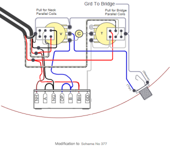
Which specific Freeway Switch and which diagram are you using?
It should be a case of selecting the switch and scheme that would work with the on-on-on switches to achieve what you are looking to do. There are certainly possibilities to do this.
Last edited:
Bruce Campbell
Junior Member
- Messages
- 182
stratamania
Mythical Status
- Messages
- 12,299
From what I can tell, this would require the neck pickup's south start wire, which is needed for the DPDT prior to the Freeway?
I am not sure what you think would mean that it cannot be used.
All you would do is take the relevant wire from the on-on-on which is the connection from the green wire on a Seymour Duncan and from there to the NG terminal of the Freeway.
The bare wire of the neck pickup normally is soldered with green, but in this case, solder the bare wire directly to ground and not to any switch.
Bruce Campbell
Junior Member
- Messages
- 182
Let me make sure I understand correctly.I am not sure what you think would mean that it cannot be used.
All you would do is take the relevant wire from the on-on-on which is the connection from the green wire on a Seymour Duncan and from there to the NG terminal of the Freeway.
The bare wire of the neck pickup normally is soldered with green, but in this case, solder the bare wire directly to ground and not to any switch.
I should jumper the connection from the lowest right lug of DPDT to that terminal on the Freeway, while retaining the connection from south start to said DPDT lug?
I wasn't sure if the signal would continue flowing or connect across the switches that way. (As Spud is so extremely fond of pointing out, I maybe don't get everything right the first time?) But if it will, that's ideal.
Thanks.
Last edited:
Spud
Master Member
- Messages
- 2,972
I never do myself. MostlyLet me make sure I understand correctly.
I should jumper the connection from the lowest right lug of DPDT to that terminal on the Freeway, while retaining the connection from south start to said DPDT lug?
I wasn't sure if the signal would continue flowing or connect across the switches that way. (As Spud is so extremely fond of pointing out, I maybe don't get everything right the first time?) But if it will, that's ideal.
Thanks.
Bruce Campbell
Junior Member
- Messages
- 182
Just emailed them with this scenario - when I receive word of a solution, I'll share the info here at that time. Good thing is at least I like the basic pickups!I found an email to freeway works pretty good. I used the same plan above, but wanted to split the humbuckers globally, and they gave me plan. I'm sure they've encountered this before. Ask for Alistar.
stratamania
Mythical Status
- Messages
- 12,299
I should jumper the connection from the lowest right lug of DPDT to that terminal on the Freeway, while retaining the connection from south start to said DPDT lug?
I will explain a little more below.
when I receive word of a solution, I'll share the info here at that time. Good thing is at least I like the basic pickups!
I have already given the solution.
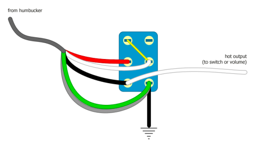
Whether you are using a DPDT for series / parallel of a pickup or an on-on-on such as below.
All you would do is take the relevant wire from the on-on-on which is the connection from the green wire on a Seymour Duncan (south start) and from there to the NG terminal of the Freeway.
The bare wire of the neck pickup normally is soldered with green, but in this case, solder the bare wire directly to ground and not to any switch.
So, using the below diagram as an example.
The bare wire shown in grey don't connect it to the switch but to the back of a pot, for example, where you have a ground.
The green wire from the humbucker connects to the switch as below
The black wire from the switch below shown as going to ground, this goes to the NG terminal of the Freeeway switch as in the diagram you supplied.
stratamania
Mythical Status
- Messages
- 12,299
To add the bare wire which shields the pickup is separated and going to ground so whatever else is happening it remains grounded, this is like when doing a Tele 4 way switching scheme. Optionally you could try it connected with the green wire, but this may create more noise in some positions.
The terminal of the switch that the green wire is connected to is also directly connected in this case to the NG terminal of the Free way. This connection is in play regardless of the position of a DPDT or on-on-on switch.
The terminal of the switch that the green wire is connected to is also directly connected in this case to the NG terminal of the Free way. This connection is in play regardless of the position of a DPDT or on-on-on switch.
Bruce Campbell
Junior Member
- Messages
- 182
stratamania
Mythical Status
- Messages
- 12,299
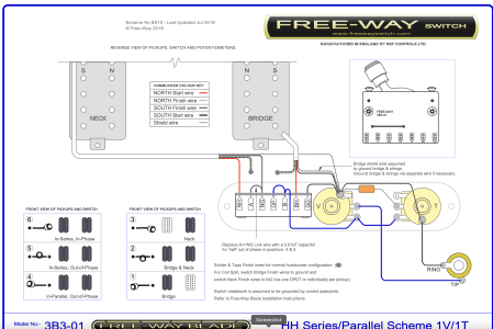
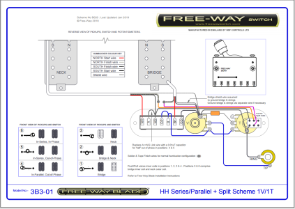
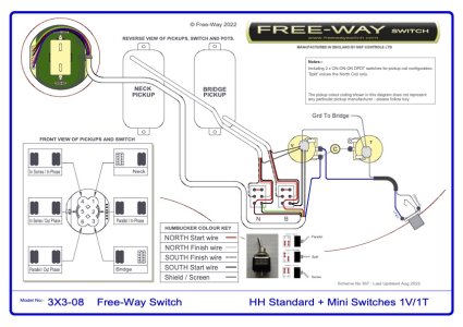
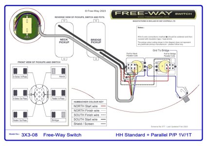
I thought you were using a Freeway blade switch rather than a toggle switch as in the first two diagrams. The last modification diagram shows effectively what I described earlier.
Bruce Campbell
Junior Member
- Messages
- 182
I am using a 3B3-01 blade, not the 3X3-08 toggle, but just passing on what Alastair sent me. The DPDT diagram earlier is appreciated, as is the diagram from manufacturer.
Bruce Campbell
Junior Member
- Messages
- 182
Hello everyone, after all this time I finally decided to change the strings - which still weren't uncomfortably worn or dead, D'Addario XS are amazing! - and redo the wiring a bit in this guitar, but went back to a regular CRL 3-way switch and did DPDT On-On switches for series/parallel within each pickup. For me the out-of-phase sounds are not very useful, whereas the parallel modes - both within each pickup and combined at the 3-way - give me the right single-coil clarity and quack. Plus, in the fury of playing, it's far easier to deal with fewer options. The Freeway switch will be nice for an upcoming Tele. Thanks again to everyone who helped with figuring this out, especially Stratamania and Rick.
Still loving the Saturday Night Special pickups, but went to an 18nf cap on the tone knob. Very slight change from the 15nf, but a nice shift.
Still loving the Saturday Night Special pickups, but went to an 18nf cap on the tone knob. Very slight change from the 15nf, but a nice shift.
Bruce Campbell
Junior Member
- Messages
- 182
Also went to a regular Fender American Standard hardtail bridge instead of the Hipshot hardtail. It intonates/sets into proper action better and more comfortably, and also sounds better to me - less harsh, more "modern" - although now, having used so many bridges & saddles, it seems that bridge tone can be as subjective as pickup preferences.
anthonyfury
Newbie
- Messages
- 17
Excellent, I did not realize that. I've messed around with the build wizard a few times and didn't find that option, but now will be exploring that.
One thing I'm working on at this point is cost - I'm not so dead set on the body wood needing to be hog/maple cap, or neck needing to be quarter sawn, and I'm kinda debating a full set of the Dimarzio Minibuckers. The Duncan SNS build that I have been laying out here might end up a separate thing.
In other words, looks like I'm actually planning 2 builds, not 1! Typical guitar player.
I don’t mean to speak for the Warmoth corp, but, just because (something) isn’t on the “regular menu” doesn’t mean they won’t do it. For one thing, there are so many hyper-specific combos / specs that the catalog could never accurately cover them all. For another thing, chances are good other customers have had an idea like yours at some point. If you have your heart set on something, call them and tell them what you’re thinking about…worst they can say is “no.”
Similar threads
- Replies
- 18
- Views
- 2K


