Leaderboard

Humbucker Cover Issues

Thanks guys.  I guess I just don't know how to make it not look like a "clusterfuk" with that many wires in such close proximity.  Do you have any advice?  

BlueFirebird, same problem.  Before I soldered the mini-switches, I didn't have a problem.  I would have tested them with alligator clip test leads, but the terminals were too small.

(EDIT): Also, getting output.  The problem is that if I disconnect the output from the bridge pickup, leaving only the neck connected, I still get both.  And vice versa.  At least I have tomorrow off.  And I'm learning a lot as I go.
 
That's alright dude, I took apart an old build that was all nice and neat, and looking at the end result of wires and parts in a wad I thought to myself "what a clusterfuk" too.  The problem may not be that hard to find.  My only advise at this point would be to print out that seymour duncan diagram and cross off and verify each connection, since the signal is getting through.  You said the three-way switch was working just fine without the extra push-pulls, right?  If that is the case, focus your attention first on how those switches are arranged on the diagram compared to your wiring first, and hopefully save yourself a chasing of the tail.  Verify everything and assume nothing.
 
I'm doing something similar.  I don't even have the switch wired in yet.  I tested my wiring there with test leads, was unsuccessful, and backed up until I realized the problem was in wiring previous to the switch

It's a good learning exercise, right?  I've learn SO much already.
 
iamdavidmorris said:
Thanks guys.  I guess I just don't know how to make it not look like a "clusterfuk" with that many wires in such close proximity.  Do you have any advice?  

The first thing I'd do is ditch the 18ga. pre-WWII appliance wire. You're only moving around millivolts at milliamps; you don't need welding cable to wire the thing up. That would buy you a ton of room all by itself. Although, from a practical point of view, very thin wire is a pain in the shorts to work with. Still, it's not like you have to wire the guitar up every time you use it. Done properly, once in a lifetime might be enough.

The original electric guitar makers from back in the '40s and '50s didn't have access to the kinds of wire we have now, so they used mostly war surplus. It was big and heavy, and the lack of plastics for insulation until the '60s or so meant they had to use bulky cloth insulation. Some manufacturers still use that stuff today for no good reason other than because many players demand it. They don't know why, they just do. Figure if it was good enough for Chet Atkins and Jimi Hendrix, it's good enough for them. Of course, those guys were pros and didn't try to stuff 32 bajillion pots and switches in their guitars, so it wasn't a big issue. Wire a pickup or two to a switch and volume/tone pot or two, and call it a love story.
 
Cagey said:
iamdavidmorris said:
Thanks guys.  I guess I just don't know how to make it not look like a "clusterfuk" with that many wires in such close proximity.  Do you have any advice?  

The first thing I'd do is ditch the 18ga. pre-WWII appliance wire.

:laughing7:

I was being nice, but I thought the same thing.  iamdavidmorris, I get 4 conductor(Red,Green, Black, White) audio cable with ground, which the cable could be a little thicker than pickup cable.  I strip and pull all of the nice color coded wires out of the cable, and BLAMO, you have matching wires of the same color codes and size as you pickup wire.  Those wires are real nice for various pickup arranging switches, but you would still want some shielded cable to the output jack.  I snagged a big coil of it when Radioshack was geared towards electronics and not selling cell phones.  I believe stew-mac or allparts would have both of the cables you seek.  I would understand if you didn't want to redo your wiring at this point, but just a thought down the road.
 
I've found that the pickup cable itself is often long enough to afford the pieces you need without having to buy any more. Nice, because multi-conductor cable is tough to get in small quantities, and large quantities can be expensive. A 100' roll of 4 conductor Belden (assuming you can find pieces that short) can easily run $50-$100, which is a helluva lot more than most people need in a lifetime.

Thing is, a lotta guys like to keep their pickup cables at shipping length in case they want to sell the pickup someday. Of course, then you have to figure out where to stuff all that extra cable, and what can you get for a used pickup, anyway? Not worth the aggravation, if you ask me. I'd much rather have a nicely-done control cavity than some kind of unserviceable and problematic rat's nest. If you've shortened the cable and want to sell the pickup, let the buyer figure out how to splice it in. That's why he's getting a deal - it's a less-than-ideal situation.

In any event, Stewart-MacDonald does have the stuff. It's roughly $16 for single conductor and $25 for four conductor, both shielded, in 25' lengths. It's way too much for one guitar. but maybe a couple/few friends might want to chip in for a piece for themselves.

 
Oh heck yes, I still have about 6' of four conductor cable I bought 8 years or so ago, but I have always hacked off a piece of wire when I needed it since then.  Twenty five foot is a lifetime supply, unless you are in the guitar wiring business, and even then it will last a long time.  :icon_thumright:
 
Right as always, guys.  I took off all that old cloth stuff and redid my work again.  It's much cleaner now.  I've wired up the mini-switches, and they work perfectly.  From here on, I can use test leads before wiring.

That cloth push back wire...  I'd seen a video where Seymour Duncan was talking about how great it is.  Maybe it reminded him of his childhood.  And the push back thing made sense to me, but experience quickly teaches you how much insulation to take off, and plastic is a superior matierial to braided cloth.

Thanks again,

David
 
I'm glad that worked out for you. It's gotta be getting a bit tiring by now, but at least it's paying off.
 
I have only had the pleasure stripping old cloth electrical wire, and it is a total pain.  I'm glad it's all coming together for you now.
 
Bit by bit.  I remind myself as I go that it's a learning project.  I have the pots wired up now, and I'll be testing them in the morning.  If all works well there, I'll do the switch next, and then the varitone.  Could be finished tomorrow.  Then it'll be time to grab the router and do some real damage.
 
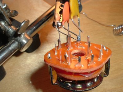
Ok.  Making progress.  The pots were working until I wired into my homemade varitone.  Now the tone pot doesn't do anything anymore.  I was hoping you guys might be willing to look at my diagram and assess whether this is probably a wiring problem or a design problem.  (Cagey, I know it's not a schematic, but the diagram is based on my own testing of the part.)

Varitone.jpg


Any ideas?

David

 
Can't tell by looking at that diagram. If I had to pose strictly a wild-assed guess, it looks like both sides of the caps are grounded. But, I don't know what's common and what's not, or how the switch works, or even what it looks like in real life.
 
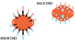
This might help a little.  There are a few ways to do it, but it looks like the safe thing to do is chose the common connection "O" of the same side( to tone pot), have one lead of each cap go to the corresponding pins, and have the other lead of the caps grounded.
 

Attachments

  • 5varitonedeluxe.jpg
    5varitonedeluxe.jpg
    123.7 KB · Views: 444
  • 3512_3512details.gif
    3512_3512details.gif
    4.4 KB · Views: 397
I realize now how unclear that picture I made is.  This is basically what I did:


Varitone2.jpg


I'd take a picture of it, but it's basically a big mess of fat wires, electrical tape, and mismatched caps.  Maybe it's time to go back to Radio Shack and get some better wire, then redo it.

General question here...  I realize the way a tone pot works is that it allows some of the higher frequencies to pass through the capacitor, and those in turn go off to ground, which is more or less like throwing them away.  As for the lower frequencies, does the cap, like...bounce them back or something?  So they go right back into that middle terminal on the tone pot and then back through the other terminal to the input of the volume pot?  That kind of makes sense to me.  Just wanted to confirm it.  Thanks.
 
That connection from pin 1 to ground is going to make that tone pot behave like a volume pot. If your intention is to bypass the tone control altogether at that position, then just leave that one open.
 
iamdavidmorris said:
I realize the way a tone pot works is that it allows some of the higher frequencies to pass through the capacitor, and those in turn go off to ground, which is more or less like throwing them away.  As for the lower frequencies, does the cap, like...bounce them back or something?  So they go right back into that middle terminal on the tone pot and then back through the other terminal to the input of the volume pot?  That kind of makes sense to me.  Just wanted to confirm it.  Thanks.

I didn't even see that you asked this until now.  The simple explaination is that the cap just drains the high frequencies more or less as the pots resistance is changed to max or min. Nothing is added, only taken away from the original signal like you said.  The more detailed expaination is that the reactance of the capacitor is the cap's resistance depending on the frequency going through it.                                The formula is:  Xc = 1/(6.284xfrequencyxCapacitor value in farads)  6.284 is really short for 2pi, but to simplify the formula...so basically if you increase the frequency, which is always a larger number than 1, the capacitive reactance decreases to a value depending on the caps value.  If you increase the capacitor's value given a frequency, which for guitar purposes is always way smaller than 1, the capacitive reactance will increase.  You would have to just plug numbers in to fully understand the relationship but basically given a capacitor , the high frequencies get to see a low resistance to ground, and the lower frequencies see a higher resistance.  The high resistance causes a voltage, which is just like the select frequencies are at full volume, and the rest get widdled down or shorted right out, according to their value.  The tone pot determines how much tone gets to stick around before the cap can have it's partial or full effect.
 
Thanks.  I didn't really know all that math, but I understand that the capacitor basically sends some frequencies to ground while allowing others to remain.  What I don't understand is the flow of electricity through the tone pot.  Here's my assumption:

The electricity enters the pot through the input terminal.  Let's assume, for now, that's one of the outer terminals, though I know it can be the inner one as well.  If the pot is at 10, it goes straight through to the opposite outer terminal, and since it's not connected to anything, and the electricity has no place else to go, it returns along the same path through the "input" terminal, and continues back to the volume pot.  If the tone pot is at 1, most or all of the electricity goes to the middle terminal, where it hits the capacitor.  Depending on the value of the capacitor, some of the frequencies will pass through the capacitor and go to ground, because that's where the other end of the capacitor is connected.  What doesn't pass through the capacitor is reflected back, as before, to the "input" terminal, where it is passed back to the volume pot.

Is that right?  I'm just asking because it will help me in troubleshooting.  I'm having some trouble with my tone pot, and I can't quite understand why.

Thanks,
David
 
Back
Top