Electric resonator with Warmoth neck

bob7point7

Senior Member
Messages
272
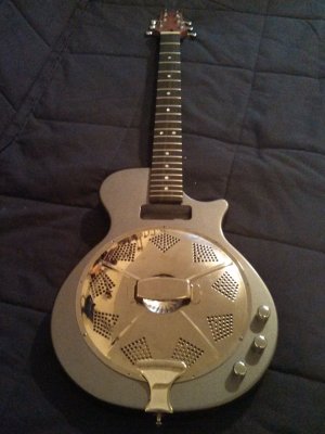
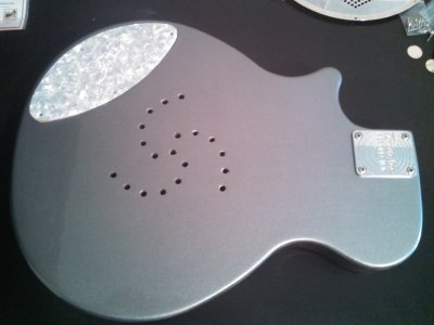
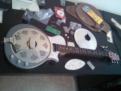
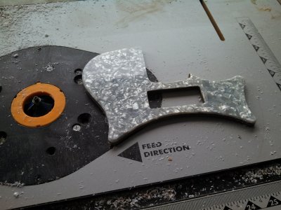
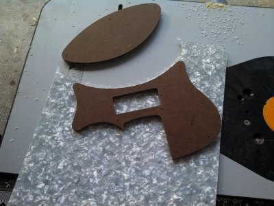
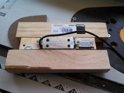
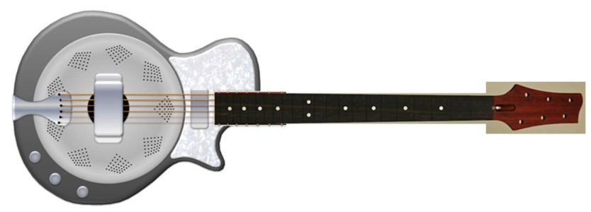
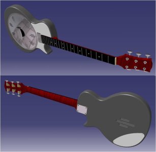
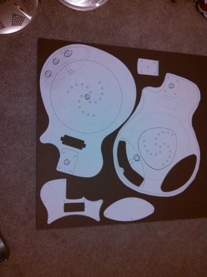
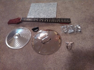
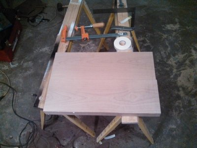
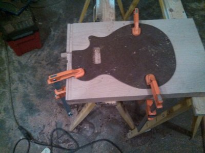
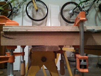
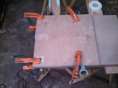
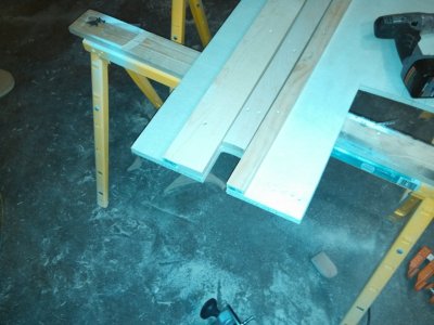
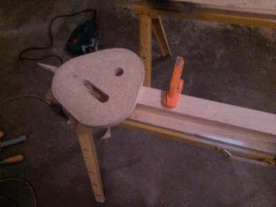
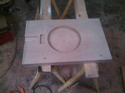
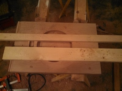
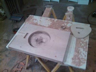
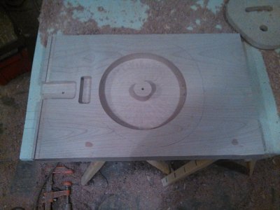
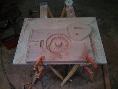
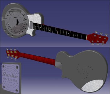
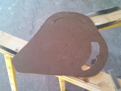
It's been quite a while since I've been active on the forum. I've actually been planning this build for over a year, but things were put on hold due to a big move new job, new baby etc. Anyway, I've finally gotten around to starting this build so I thought I would share the progress. The first picture shows the initial powerpoint sketch that started the whole thing. The next pic is of the CAD model I made to figure out the body geometry. I've refined the shape a little since these screengrabs were taken but you get the point. The third pic shows the templates that I generated from the CAD model. Pic four shows the parts collected including the padouk/ebony neck with Warmoth headstock. Pic five is the alder body blank.
 

Attachments

  • res sketch.jpg
    res sketch.jpg
    34.3 KB · Views: 31
  • res model.jpg
    res model.jpg
    33.4 KB · Views: 23
  • templates.jpg
    templates.jpg
    140.3 KB · Views: 18
  • parts.jpg
    parts.jpg
    164.8 KB · Views: 23
  • body blank.jpg
    body blank.jpg
    54.6 KB · Views: 11
I started out by making a neck pocket jig. I cut the 5" radius for the neck heel into the end of a 2" board (pic 1), then screwed it to plywood with 2 other boards along side the neck (pic 2). I routed inside the boards with a pattern bit to make the neck pocket jig, then clamped it to the blank with shims under the back so the neck would end up at a 1 degree angle (pics 3 and 4). After the neck pocket was routed a used one of the templates to route for the pickup (pic 5).
 

Attachments

  • pickup routing.jpg
    pickup routing.jpg
    164.1 KB · Views: 9
  • neck angle.jpg
    neck angle.jpg
    160.6 KB · Views: 3
  • routing neck pocket.jpg
    routing neck pocket.jpg
    149.3 KB · Views: 4
  • making neck pocket jig.jpg
    making neck pocket jig.jpg
    157.9 KB · Views: 3
  • neck pocket radius.jpg
    neck pocket radius.jpg
    149.4 KB · Views: 11
Next it was time to route the pocket for the resonator cone. The hole needed to be 9.5" diameter and 1.25" deep. I made a circle cutting jig and started hogging out material (pics 1 and 2). Once I had the depth right I cut most of the center out with a die grinder and cutoff wheel (pic 3) and finished it off with the router (pic 4). The final pic shows the blank with neck pocket, pickup route, and resonator route. More to come soon!
 

Attachments

  • cone routing 5.jpg
    cone routing 5.jpg
    150.3 KB · Views: 17
  • cone routing 4.jpg
    cone routing 4.jpg
    132.2 KB · Views: 5
  • cone routing 3.jpg
    cone routing 3.jpg
    139.6 KB · Views: 7
  • cone routing 2.jpg
    cone routing 2.jpg
    167.3 KB · Views: 7
  • cone routing 1.jpg
    cone routing 1.jpg
    152.4 KB · Views: 12
Interesting project. Good planning on the cuts - that blank has to be easier to deal with than a body that's been shaped.
 
I Love it , I've been thinking about building one for years ...this should be killer!  :headbang1:
 
It's been a while, but here's an update on the project. The first attachment shows the latest 3D CAD model I've been using. I'm really hoping to get a neck plate from Doug for it. The next pic is of the templates for the control cavity and cover. The space for the cavity is pretty tight since it has to stay clear of the cone and house a preamp and battery. The third pic shows the template in use. Finally there's a pic of the finished control cavity.
 

Attachments

  • elec res Jan 2014.jpg
    elec res Jan 2014.jpg
    68.8 KB · Views: 9
  • control cavity template.jpg
    control cavity template.jpg
    87.9 KB · Views: 2
  • routing cavity.jpg
    routing cavity.jpg
    114 KB · Views: 3
  • control cavity.jpg
    control cavity.jpg
    82.5 KB · Views: 6
The next step was to (finally!) cut the body from the blank. I cut it about a 1/4" large then used a pattern bit and template to route the final shape, but I forgot to take photos of this. Unfortunately I got some tearout due to my lack of experience. By the time a figured out a good technique I'd already done some damage to the body. I was already planning on painting the body a solid color so I just filled in the tearout with some body filler. After a little final shaping I routed the edges. I also drilled holes in the back of the body to allow air behind the cone in and out. All that's left is to drill for the neck screws and output jack, then it's time for primer.
 

Attachments

  • mockup.jpg
    mockup.jpg
    112.2 KB · Views: 27
  • rear with routed edge.jpg
    rear with routed edge.jpg
    73.3 KB · Views: 19
  • front with routed edge.jpg
    front with routed edge.jpg
    80.8 KB · Views: 17
  • body cutout.jpg
    body cutout.jpg
    95.4 KB · Views: 6
Nice! That's going to be a real showpiece!

I sympathize with the tearout problem - I used to get it from time to time, particularly with Maple. But, I found out that what you need to do plot your cuts so you can "climb cut" some areas around the piece, and "pull cut" others. It involves finding the grain direction and having good control of the router. There's a good article on it here if you're interested.

Helped quite a bit when I cut for the binding on the L5S in my sig. Not a single tearout on either side.
 
Thanks Cagey! That article on climb cutting is great - I wish I would have read it before I routed this body.  :icon_smile:  The next project won't be painted so these sorts of errors won't be tolerable. Glad I'm learning now!
 
A number of years ago I bought an acoustic Resonator with a pressure mic on the pan, I dropped a Dano Lipstick tube at the base of the fingerboard with a split 500k pot I used to blend the two.

This is by far WAY more awesome! :headbang1:
 
I know I haven't updated this post in forever, but things got put on hold for a kitchen remodel and other craziness. I actually got paint on the body in March. I used Rustoleum sandable fill primer to fill the grain, followed by their regular automotive primer for the second coat. This got me to a really smooth surface in pretty short order. I wanted a really glossy and durable finish so I ordered a can of urethane basecoat in an aerosol can from automotivetouchup.com. The color is Honda Silverstone. It went beautifully but it was very thin. I had sanded the primer with 400 and if you look in the light you can see the 440 grit scratches under the basecoat. Next time I'll use 600 grit before spraying the basecoat. For the clearcoat I used a can of SprayMax 2K urethane. This stuff comes in an aerosol can with a can of hardener made inside it. When you're ready to use it you take the red piece out of the cap, put in on the bottom of the can, and slam it on the table to puncture the inner can and release the hardener. It has a 24 hour pot life after the hardener is released. This stuff went on really nice but I got a little carried away on the back and got some sags. Once it hardened up I was able to sand and buff it to a pretty nice finish. I've attached pics of each stage.
 

Attachments

  • primer front.jpg
    primer front.jpg
    142.7 KB · Views: 6
  • basecoat front.jpg
    basecoat front.jpg
    213.1 KB · Views: 6
  • clearcoat front.jpg
    clearcoat front.jpg
    179.1 KB · Views: 6
  • clearcoat rear.jpg
    clearcoat rear.jpg
    127.4 KB · Views: 8
  • mockup after paint.jpg
    mockup after paint.jpg
    155.5 KB · Views: 28
The next step was to make the pickguard and rear control cover. I made templates from masonite and cut the pieces out of a piece of Warmoth pearloid pickguard material on the router table. I used a straight pattern bit for the initial cutting then beveled the exposed edges of the pickguard with a 45 degree bit. I found a little 1/4" diameter laminate trim bit that worked great for finishing the corners of the pickup hole. The whole process went fairly smooth. Pics are attached below. In the control cover pic you can see the neck plate Doug machined for this. As expected he did awesome work.
 

Attachments

  • control cover mockup.jpg
    control cover mockup.jpg
    105 KB · Views: 13
  • pg mockup.jpg
    pg mockup.jpg
    150.8 KB · Views: 15
  • pg routing 2.jpg
    pg routing 2.jpg
    178.6 KB · Views: 7
  • pg routing 1.jpg
    pg routing 1.jpg
    169.7 KB · Views: 3
  • pg template pickup routing.jpg
    pg template pickup routing.jpg
    140.7 KB · Views: 5
This looks great! I love the idea.

I wonder though- is the resonator simply for looks or will it have effect on the sound?
From what I've picked up most of the effect in electrics are from the pickups, but this is more than a change of wood..What were your intentions for it?
 
Very cool Bob, nice cad work, what software did you use? And the reso-git looks pretty sweet... :icon_thumright:
 
Thanks for the kind words guys! The resonator definitely changes the sound. I used to have a cheap import electric res and I've missed that sound ever since I sold it. The piezo on the cone itself gives the resonator sound but will probably sound pretty thin and trebly by itself. The neck pickup will likely sound much more like a traditional electric but with a little resonator sound. The trick is to have an active preamp that allows the two signals to be blended. You can get the meatiness from the magnetic pickup and the "cone tone" from the piezo. I added an active blender to the import res I had and it came to life. I'll be sure to post sound clips once it's done. (If I ever get this kitchen finished!) I used CATIA for the CAD modeling. Mostly it was for fun but it has been really handy for making templates and figuring out neck angle.

-Bob
 
Well, it has taken a ridiculously long time, but this thing is finally done! The fist pic shows the pickups and wire routing. The neck pickup is a Dimarzio vintage mini humbucker and the cone has a pair of JJB piezo pickups attached. The second pic shows the cone and biscuit setup. The third pic is inside the control cavity. Both pickups go to a blend pot (both full on in the center) then to a dual buffer that's built off the AMZ multi-purpose opamp board shown here: http://www.muzique.com/tech/opamp_multi.htm

After the buffers both signals go through mixing resistors then to a tone circuit and master volume. The JJBs do a great job of picking up the sound of the resonator cone but they're very prone to feedback. The mini hum has a nice sound but is closer to a typical electric. So far I find myself having the blend knob close to the middle at lower volumes and turning it towards the neck pickup as I get louder to prevent feedback. It's nice to be able to roll off the highs just a little bit with the tone knob when there is a lot of piezo in the mix. The final 2 pics show the competed guitar.
 

Attachments

  • pickup wiring.jpg
    pickup wiring.jpg
    73.3 KB · Views: 16
  • setup.jpg
    setup.jpg
    53.3 KB · Views: 15
  • preamp.jpg
    preamp.jpg
    78 KB · Views: 17
  • on hanger.jpg
    on hanger.jpg
    31.9 KB · Views: 17
  • with amp.jpg
    with amp.jpg
    65.6 KB · Views: 42
Back
Top