What is the basic concept of guitar wiring?

WindsurfMaui

Senior Member
Messages
329
I'm trying to learn how to do complex (to me) guitar wiring. I'm not an electrician so I always thought the electrical wiring in a guitar worked like water it flowed in and then had to flow out. That is there is an input wire and then an output wire  on any switch. But as I look at various wiring diagrams I see that  there are times that tone pots only have one wire connected to it's lugs. And I can't wrap my head around how the input wire to that tone pot is also the output wire from the tone pot and how it effects the sound. Water can't flow down and then back up (as far as I know). So can someone enlighten me in non electrical engineering terms the concept of how the charge flows through the guitar switches? Specifically how does a tone pot work if it only has one wire connected to it? Thanks
 
Check out the sticky at the top of this forum.

A very useful link is this one.

https://www.seymourduncan.com/blog/latest-updates/guitar-wiring-diploma-course

The signal to the tone pot does not come back out again it is bled off to ground. That is also covered in the series of articles that can be found in the above link.
 
Here too ... https://www.fralinpickups.com/2017/03/03/volume-tone-pots-101/
 
WindsurfMaui said:
But as I look at various wiring diagrams I see that  there are times that tone pots only have one wire connected to it's lugs.

The Tone pot serves one purpose — bleed signal to Ground. One lug connects to HOT (the wire), another lug another connects to GROUND (the back of the pot).
 
I'm reading everything I can find but most of the places skip steps because they understand the concept but people like me don't. Some times pots have in wires and out wires and sometimes they don't. DPDT switches have input side and output side but what exactly is being sent out depending on which lug you connect to?? I need a basic high school priimer on  how electricity/sound travels through these parts.
 
Try the Seymour Duncan link. Go through each bit one step at a time, draw them out figure out what is going on.

Don't read everything to the point of confusion take it one step at a time till you really understand each element before moving on.

It is also no good just looking at how wires connect to a switch you need to be able to understand how that switch works mechanically and fully to be able to figure out what is happening otherwise it will just look like spaghetti and not taste as good.

 
stratamania said:
Try the Seymour Duncan link. Go through each bit one step at a time, draw them out figure out what is going on.

Don't read everything to the point of confusion take it one step at a time till you really understand each element before moving on.

It is also no good just looking at how wires connect to a switch you need to be able to understand how that switch works mechanically and fully to be able to figure out what is happening otherwise it will just look like spaghetti and not taste as good.

I quite agree with stratamania, that's good advice on how to look at it. When I was a machinist I would often be given a blueprint to follow. Most times that print dealt with the entire assembly we were making. it could be overwhelming to say the least. I learned to only look at the first part I had to do, when that was done then the second part, and so on down the line. It kept down the confusion to only concentrate on specific points, and learn them before moving on... :icon_thumright:
 
  Stratmania, PhilHill I agree completely. One of the problem is I don't understand the basic properties of the underlying current. I understand water it moves by pressure or gravity goes in one place and comes out another, Electrical current is still a mystery. I thought tone was effected by a tone pot by the tone current going in on one lug and out on another and changed by where the tome pot dial was turned. But now with only one wire the tone pot and capacitor sends it signal (adjustment) to the signal current somewhere else. Still wrapping my head around that. As you can see understanding  electrical stuff doesn't come easy to me. But it is still fun. Thanks
 
For the concept of a normal tone pot, view ground as the out.
As you turn the tone pot off max, it bleed higher freq to ground. 

View the completion of most electrical circuits as ground.  It is not viewed as in or out, just a completion of the circuit.

Does that help?
 
Thinking about electricity like water flowing thru a pipe system helps me understand it too.  Actually, for most things envisioning the process as a system of pipes, understanding where things are going, then looking at contents flowing thru the pipes.  Like music, understanding where the parts go, then understanding what's going on within those particular segments. 

 
Here is the closest I can get to ELI5 ("explain like I'm 5"). We are going to ignore things like AC voltage and current because they are not necessary to explain these controls. I'm also ignoring the resistance calculations of the voltage-divider circuits for a more high-level explanation. I made a few diagrams, with some help from royalty-free vector images for the PU and knob.

Just remember...voltage always heads toward Ground. It's so important, I'm making it a proper noun. No Ground, no work-y. For these exmaples, we assume the guitar is always connected to an amp with a traditional cable.

Without any controls... the PU is hardwired to the amp, all the signal goes to the amp to find Ground.
lrseu68.png


Electricity always takes the path of least resistance. If we were to short the pickup HOT to Ground within the guitar, all the signal would dump to ground.
PznDcrx.png


But if we add some resistance, in this case a 500K resistor, most of the signal decides it's easier to head to amp and find a easier path to Ground. Yet, notice some signal does bleed through to Ground. Smaller resistors let more signal bleed to Ground, larger ones let less bleed through.
TBx6j0S.png


If we replace that fixed resistor with a variable resistor (our Volume pot), we can control how much signal goes to the amp and how much goes to Ground.

At "10", we have maximum resistance to Ground...
U2AKnhZ.png


As we turn the Volume pot down, we decrease resistance to Ground...
u4HK30i.png


Until we short the entire signal to Ground...
IBRioE2.png


Some notes...

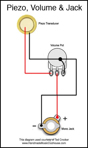
Note that Volume pots have one input and TWO outputs...one Hot, one Ground. In the real world, one lug is usually soldered to the back of the pot and connected to Ground. Unlike the rest of the images here, I did not create this one, but it has its credit on the image, so I'll borrow it.
1546aff80a65c24bb02be9bad0870306.jpg


The pot value controls how much signal goes to the amp and how much goes to Ground when the knob  set to "10." But there is a side-effect, the high-end treble. Selecting the right pot is all about tuning the control and tone to taste.

  • Large pots, like 1M or 2M, will send a hotter and brighter signal to the amp
  • Small pots, like the 250K used by Fender, send a weaker signal to the amp, but can tame the excessive treble of the single coil PUs

I have to get back to the day job, so I'll leave this open for questions and add an explanation for Tone controls later.
 
I've been having some difficulty in coming up with how to best illustrate the high- and low-pass process of capacitors, so this is taking a while.

Capacitors block all DC voltage, the DC voltage can't get through and has to find an alternate path to ground (remember a path to Ground has to be present, or this doesn't work) ...
kvNSgMs.png

Traditional guitar electronics have no DC voltage in them, I only point out the above behavior to say that the reason DC voltage can't get through is because it is positive all the time.

Guitar pickups generate AC voltage, all audio signals are AC voltage, this is because they both share the same sine wave structure. Because AC alternates between positive and negative, a capacitor doesn't block all AC voltage, it only blocks the slower lower frequencies, the faster higher frequencies pass right through.
s0pJq1T.png


We can steer the process and connect the capacitor to Ground, making it the path of least resistance. It will pass the high-end frequencies to Ground and the low-end by bypass and keep on keeping on.
olr5d6F.png

The "size" (capacitance rating) of the cap determines the frequency pass-though.
FRVSQSK.png


In a guitar, that would look like this...which is a simplification of what the tone cap does in a guitar.
YiPxDch.png


Now we add our resistance, our Tone pot that controls resistance to Ground. Just because the high-end frequencies can pass through the capacitor doesn't mean they have to...if there is a easier path to Ground elsewhere, they'll go elsewhere...
Trj3fjo.png


Note the Tone control only has two connections. It serves a single purpose...shunt-high end to Ground. So it has input from Hot and output to Ground. The rest of the signal will decide the path of least resistance is through the Volume pot and on to the amp. I can't put the arrows on this one, it gets too confusing.
hleRJNr.png


That's the basic guitar wiring still in use from the 1930s.

Because the circuit always bleeds some signal and high-end to Ground, we pick the pot values and cap values for optimal tone/performance on "10" and for the behavior we want when turning down.

We can go on to discuss thing like G&L's Treble/Bass tone controls and Treble Bleed mods, but they are all variations on the above concepts, caps are use to steer set high frequencies one direction or another.
 
Back
Top