Leaderboard

Tube amp guru's....help

DangerousR6

Mythical Status
Messages
15,478
O.K. you tube amp modders and prodders, I got a problem with my Blue VooDoo 6212. It seems that it keeps blowing a 1/4 A fuse. It started out blowing one occasionally, now it's popping almost as soon as I turn it on. I've got a schematic, here's a pic of it, it's the fuse right above the power tubes..
 

Attachments

Warning - this is a guess.

I believe that the fuse is in-line with the B+ rail supplying the plate voltages.  Points to a tube short.

replace the output tubes and see what happens.

Trevor
 
That's not a schematic, that's a parts layout. There's supposed to be a schematic available here, but the site's down at the moment. So, it's tough to say what's going on. But, if as Trevor says, it's the B+ for the plate supply fuse that's opening, it could be a short in either a power tube or the output transformer.

Note that the plate supply is high voltage DC, so be SURE you have the thing unplugged and the filter caps discharged before you start fiddling around in there.
 
http://www.webphix.com/schematic%20heaven/www.schematicheaven.com/newamps/crate_bluevoodoo_60w.pdf
There's the link Cagey was posting... except functional :P
 
Cagey said:
That's not a schematic, that's a parts layout. There's supposed to be a schematic available here, but the site's down at the moment. So, it's tough to say what's going on. But, if as Trevor says, it's the B+ for the plate supply fuse that's opening, it could be a short in either a power tube or the output transformer.

Note that the plate supply is high voltage DC, so be SURE you have the thing unplugged and the filter caps discharged before you start fiddling around in there.
Yes I realize it's not the schematic but just a layout drawing, I already have the actual schematic but thanx. Yes power is unplugged....


Superlizard said:
Is this the same issue you had a while ago (we discussed)?  I don't remember (senility).
Yes it is, I've had it on the back burner. And finally got some time to fiddle with it...
 
On page 5 of the schematic, it appears that there are some resistors to ground after the rectifier coupled to the first filter caps.  If you give the amp a minute or two, it should release the potential stored in the filter caps.  Still, best to check with a voltmeter before getting that unexpected shock.  As far as that fuse goes, it is in the path of the cathode return to ground (page six J205 and J206, page seven J13 and J14 wire #2 on both)  Mayfly's comment seems the most likely.  There are not that many options to cause that fuse to go.  You need the power (The other side of the tube) and it has to get to the fuse (a short in the tube.)  If you do go in and look, make sure to shop vac out any dust, or other things, that may be in there.  Good luck
Patrick

 
Patrick from Davis said:
On page 5 of the schematic, it appears that there are some resistors to ground after the rectifier coupled to the first filter caps.  If you give the amp a minute or two, it should release the potential stored in the filter caps.  Still, best to check with a voltmeter before getting that unexpected shock.  As far as that fuse goes, it is in the path of the cathode return to ground (page six J205 and J206, page seven J13 and J14 wire #2 on both)  Mayfly's comment seems the most likely.  There are not that many options to cause that fuse to go.  You need the power (The other side of the tube) and it has to get to the fuse (a short in the tube.)  If you do go in and look, make sure to shop vac out any dust, or other things, that may be in there.  Good luck
Patrick
I usually let it rest for and Hour to make sure it's discharged. Is it possible it could be a bad pre amp tube, J13 and J14 are preamp tubes. The power tubes were just replaced not more than a few months ago, with virtually no play time on them. .... :dontknow:
 
Max said:
http://www.webphix.com/schematic%20heaven/www.schematicheaven.com/newamps/crate_bluevoodoo_60w.pdf
There's the link Cagey was posting... except functional :P
That's for the BV 60 head, mines the combo. There's a few differences in the head and the combo. :icon_thumright:
 
In this case, J13 and J14 refer to the jumpers from the main board to the power tube board.  I think that they label them with two distinctions to eliminate confusion about which board connections, and tube for that matter, they refer to.  It shows a 13 pin connection, with not all of the pins being used.  It is in the bottom right hand section of page 7.  But from the description you gave, and the diagrams posted, this fuse is only in line with pin 8 from a power tube.  Unless something very odd has happened, it really isolates the problem to the power tube.  Do you have any other 6L6's you could swap in?  If the fuse lasts with the new (other) tube it would lead me to believe that the suspect tube had something go funny with it.
Patrick

 
Patrick from Davis said:
In this case, J13 and J14 refer to the jumpers from the main board to the power tube board.  I think that they label them with two distinctions to eliminate confusion about which board connections, and tube for that matter, they refer to.  It shows a 13 pin connection, with not all of the pins being used.  It is in the bottom right hand section of page 7.  But from the description you gave, and the diagrams posted, this fuse is only in line with pin 8 from a power tube.  Unless something very odd has happened, it really isolates the problem to the power tube.  Do you have any other 6L6's you could swap in?  If the fuse lasts with the new (other) tube it would lead me to believe that the suspect tube had something go funny with it.
Patrick
Alrighty then, I have a set of EL34's that were in it when I got it, I guess I could but them back in. :dontknow:
 
DangerousR6 said:
Patrick from Davis said:
In this case, J13 and J14 refer to the jumpers from the main board to the power tube board.  I think that they label them with two distinctions to eliminate confusion about which board connections, and tube for that matter, they refer to.  It shows a 13 pin connection, with not all of the pins being used.  It is in the bottom right hand section of page 7.  But from the description you gave, and the diagrams posted, this fuse is only in line with pin 8 from a power tube.  Unless something very odd has happened, it really isolates the problem to the power tube.  Do you have any other 6L6's you could swap in?  If the fuse lasts with the new (other) tube it would lead me to believe that the suspect tube had something go funny with it.
Patrick
Alrighty then, I have a set of EL34's that were in it when I got it, I guess I could but them back in. :dontknow:

Yep  -that's what I'd try.  and if that works, take the new ones back.
 
Call me kooky and senile cuz I don't 'member the specific rules, but since when can one just swap out EL34s for 6L6s without making some adjustments?  (plate voltage etc)
 
Reading this all again, I have some questions:

there were EL34's in an amp designed for 6L6s?  That's gonna be hard on your heater windings (EL34s have about double the current requirements of 6L6s)

If the EL34s do work and the 6L6s don't - check to see that the amp has not been modded to boost the plate voltage.  If it has and your plate voltage is over 450, that will eat your 6L6s.

Hmmm - do you have photos of the insides of this thing?
 
Superlizard said:
Call me kooky and senile cuz I don't 'member the specific rules, but since when can one just swap out EL34s for 6L6s without making some adjustments?  (plate voltage etc)
I'm no expert at this, but the amp had el34's in it when i bought it.....This amp is "self" biasing, there's no adjustment pots for the tubes, and also the guy I spoke with at Eurotubes said that the EL's would be fine...But someone else told me the EL's would be to hot, so I got the 6L6's, changed the fuse and played for about 5 minutes the silence..... :dontknow:
 
mayfly said:
Reading this all again, I have some questions:

there were EL34's in an amp designed for 6L6s?  That's gonna be hard on your heater windings (EL34s have about double the current requirements of 6L6s)

If the EL34s do work and the 6L6s don't - check to see that the amp has not been modded to boost the plate voltage.  If it has and your plate voltage is over 450, that will eat your 6L6s.

Hmmm - do you have photos of the insides of this thing?
I'll take some photos of it....
 
DangerousR6 said:
Superlizard said:
Call me kooky and senile cuz I don't 'member the specific rules, but since when can one just swap out EL34s for 6L6s without making some adjustments?  (plate voltage etc)
I'm no expert at this, but the amp had el34's in it when i bought it.....This amp is "self" biasing, there's no adjustment pots for the tubes, and also the guy I spoke with at Eurotubes said that the EL's would be fine...But someone else told me the EL's would be to hot, so I got the 6L6's, changed the fuse and played for about 5 minutes the silence..... :dontknow:

The pinouts for EL34s and 6L6s (as well as a few others such as 5881s and KT77s) are all the same, so it's not like you're going to blow anything up. But, the characteristics of the tubes are different, so they need to be biased differently and in some extreme cases, the plate voltage needs to change. In the short run, you can get away with murder, but the thing you're liable to murder is the tube itself, and they aren't cheap.

Power tubes are rarely "self-biased", as there's too much at stake to let things adjust themselves. If there's no adjustment, it's unlikely the chassis is meant to take tubes other than those it's designed for.
 
mayfly said:
Reading this all again, I have some questions:

there were EL34's in an amp designed for 6L6s?  That's gonna be hard on your heater windings (EL34s have about double the current requirements of 6L6s)

If the EL34s do work and the 6L6s don't - check to see that the amp has not been modded to boost the plate voltage.  If it has and your plate voltage is over 450, that will eat your 6L6s.

Hmmm - do you have photos of the insides of this thing?
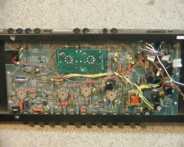
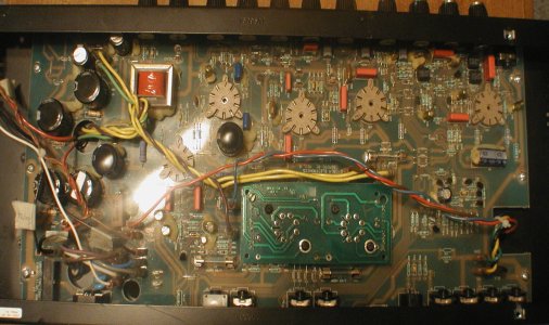
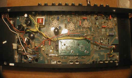
Pics..

The rectangular darker green board is the power tubes, the fuse right adjacent to it is the one blowing out...
 

Attachments

  • Crate guts.jpg
    Crate guts.jpg
    289.9 KB · Views: 420
  • Crate guts 2.jpg
    Crate guts 2.jpg
    383.4 KB · Views: 476
  • Crate guts 3.jpg
    Crate guts 3.jpg
    341.3 KB · Views: 663
Back
Top