monchavo
Junior Member
- Messages
- 59
I have a build I'm revisiting after five or six years. It's got a beautiful vintange tint Warmoth neck (with what they call "bonus birdseye!".
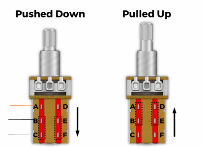
The bridge pickup is supposed to be a tappable single coil. Based on the SSL-5 it has three wires - black, white and yellow. I've looked for suitable diagrams online to connect it to a tone control push-pull pot without success. Even the useful Fralin push-pull resource doesn't seem to quite have what I need. A fine trove however: https://www.fralinpickups.com/2017/03/29/push-pull-pots-mods/
Two questions: Unfortunately the pickup winder chap I bought them from is MIA. Supposing the pickup is a direct copy of the Seymour Duncan unit, I could just measure it with my multimeter (ill do this in a moment) and that will give me readings indicating which the "hot" and "cooler" wire is - but I am not clear how I would connect these successfully to achieve the tap. I would like down to be tapped and UP to be full throated (like a sort of "pull to boost" arrangement).
thanks !