Resistor values for messing around

tfarny

Master Member
Messages
4,481
Just a quick Q for those who know their electronics - I'm going to start messing with different cap and maybe resistor values to make my own varitone-type tone control for my bass and then maybe for my other axes. Just got back from Radio Shack where I picked a bunch of caps from .1uf to .001uf and some alligator clips. I'd like to have maybe one setting which just simply mimics the constant load of 2x 250k pots and maybe a tiny cap on there to take the edge off. One setting will be full bypass, but I'd rather have a default setting that mimics a 'normal' jazz bass setup. The only pot in the circuit will be a 500k master volume.
I may experiment with some bigger values as well, I'm going to set up a little box and play around till I get something I like.
So, what resistor values (watts and ohms) are useful for tweaking passive pickup signals in this way? I'll just go and pick up several of the most likely suspects and play around with them. Thanks in advance.  :icon_thumright:
 
This is kind of difficult to answer because the pedals/amp also play with the impedance load on the pick up.  To see what happens when you put a high impedance load on a pick up, listen to these vid/links...

http://media1.zvex.com/superhardon.mov
http://media1.zvex.com/superduper.mov

My computer at work will not allow for viewing anything fun, the IT guy is a Grinch, but I know that these pedals have a high impedance load (a 1 to 10 meg resistor to ground across the input jack.)  I cannot remember which vid shows that aspect of the pedal.  So changing the loads in the guitar or bass will have an effect, but then there is the cumulative load from the down stream effects or amps.
Patrick

 
I've played a good deal with this type of thing...

It almost always works better, when used with an inductor, even a small one, to balance the inductance (or partially so) of the pickup.

Cap values to play with:

500pf
.001
.0015
.002
.0047
.01
.02
.047
.1

In the smaller cap values, placement in the circuit matters a WHOLE LOT, due to the added capacitance of the guitar cable itself... which is where things get tricky, because if you change cable or length... it all flies out the window.

Inductance of about 1hy to about 2hy work for traditional varitone.  I've seen 900mhy work, and 2.4hy work. 

You need to put a load resistor in series with the signal - something of 10k to about 200k max but think in terms of 47k to 100k as middle of the road values.

And finally, it all GREATLY depends on the inductance, impedance, overall tone response and output of the pickup.  What sounds killer in one setup, is terrible in the next - been there and done that!

If you can get the old Bill Lawrence schematics and how to's, get them - he was THE WIZARD of this stuff, much to be learned there.

Generally, as the impedance goes up, the frequency of the filter will go down.  You want to control the inductance such that it just breaks into the main "sparkle" range of the pickup - Higher than 2nd order harmonics.  Get into the 2nd order, you got mud, lower and you just knock the signal for a big one.
 
I probably should add... get hold of two (not one) Qfilters from Lawrence.  Then get a 250k pot to act as the load resistor, and then have fun... and it is fun too.
 
Thanks man! I might not get as far as all that, and I may just end up doing a rotary 'tone switch' and not an actual varitone-type. Maybe I'll do a rotary tone switch and get into "real" varitone stuff later on. I have a nice bass eq pedal for mid scooping already. I'm actually trying to both simplify the switching and expand the 'good' tones I can get out of one passive bass. I appreciate the input though and I'll try and get a q-filter or two.
 
=CB= said:
I probably should add... get hold of two (not one) Qfilters from Lawrence.  Then get a 250k pot to act as the load resistor, and then have fun... and it is fun too.
Hmm, those look interesting.

http://guitarsbyfender.yuku.com/reply/13960/t/Q-filter-What-does-it-do-exactly-.html#reply-13960
 
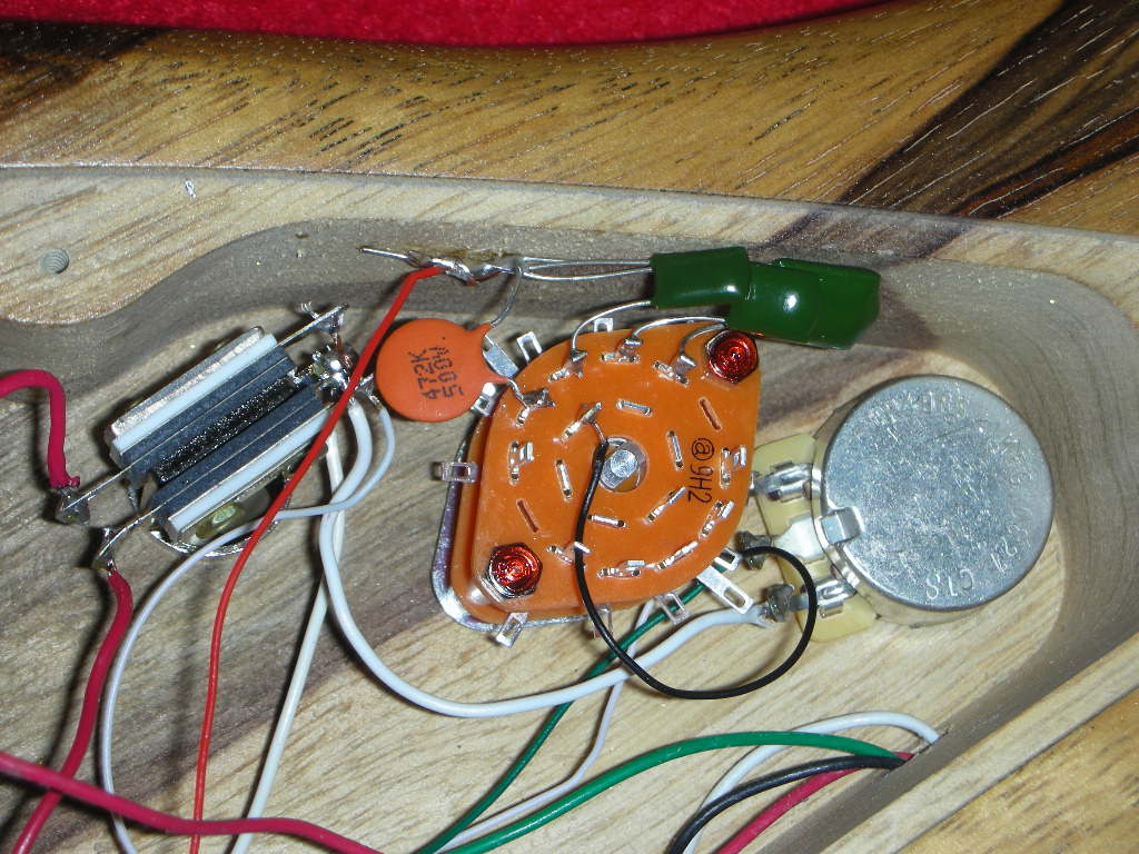
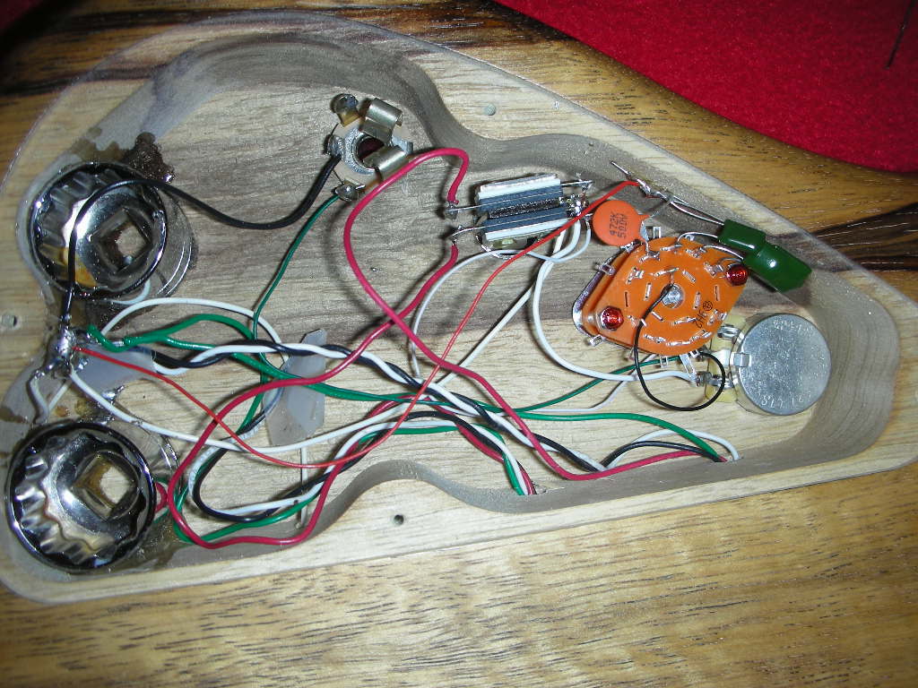
OK, I got this together last night and it is definitely an improvement over a stock tone control. I really like this new setup. It is 1) simpler than my old blend / vol / tone setup and 2) more versatile - I have both treblier and bassier tones available. I also put little dots on my knobs so I can actually see what I'm currently on.
Now its: Master vol / Rotary tone switch / Gibson pickup toggle. Rotary tone goes: 1) wide open, [trebley good for slapping] 2) .0047 cap [close to typical sound] 3) .01 cap [rock] 4) .022 cap [old school] 5) .1 cap [Rasta]

The wiring looks messy but is actually neat - all grounds go to a central spot in back which is just a wood screw. The two sockets epoxied in there did the trick to balance it.     Wenge / ebony necks!!!!! (shakes fist like Stephen Colbert).
4220273582_73c8f75612_o.jpg

4220273440_790bf10fc2_o.jpg
 
are those sockets super glued in there to help balance the weight of the neck? My Warmoth is a semi-hollow and the neck is all rosewood and it is a bit neck heavy. How does this solution work out for you?
 
when you said 2 250k pots did you mean 2 volumes or 1 vol 1 tone?
if you are talking one vol one tone just add a 500k resistor that goes hot to ground for 250k. and another in series w/ a cap hot to ground. you may be able to use lower value components for the tone and get the same result but you cant go wrong w/ 250k and what ever the stock tone cap would have been

if you are talking 2 volumes you add the reciprocals then take the reciprocal of the sum. so the math for resistence value looks like this:
1/250k + 1/250k = 2/250k = 1/125k


1/500k + 1/Xk = 1/125k
1/500k + 1/Xk = 4/500k
  -1/500k            -1/500k
1/Xk = 3/500k
Xk = 166.667k
so 166k in parallel with 500k is equivilent to 2 250k in parallel. also 500k and 250k resistors in parallel or 3 500k would work.
that is if you still want to simulate stock wiring.

the difference between using resistors and using a small cap will be that the cap only will be slightly louder, more upper mids and maybe more sensitive to the influance of long cables. that last part is kinda a guess. but you may find your cap choice to be an improvement over stock and not want to simulate it any more presicely.
 
Thanks. It had a 500k/500k blend, 500k master volume and 500k tone, which is all gone and replaced by one 1 meg master volume. The .0047 cap I have in position two does enough to take the edge off that I'm not really interested anymore in really mimicing the load of all those pots. For me it's about the end result and I like the .0047 cap sound as much or more as the previous setup "wide open". But it's good info to have when / if I do this on a guitar.

The .1 cap sounds cool on my own GK amp, great for reggae / dub sounds which are fun once in a while. But through an ampeg SVT its' a joke - most people might be happier with a .047 cap in that position.

And: yes the sockets are there for balance. The hipshot tuners took care of 75% of the balance issue, these took care of the other 25%. It's a pretty heavy bass, but it was heavy before I got these anyhow. Next bass will be lighter.
 
the math is the same for caps in series. you could do that job with fewer component that way, but i must say you did a great job of keeping it clean. i would have messed it up by getting complex somehow. 
 
If I remember correctly, adding cap values is opposite of adding resistive values.  In other words, two caps in parallel, they add together.  When adding in series it's like adding ohm values in parallel. 
 
absolutely right.
read closely i said it was the same method for "caps in series."

resistors or inductors in series just add
"                              " in parallel add reciprocals and then take the reciprocal of the sum

caps in parallel just add
caps in series add the reciprocal and the take the reciprocal of the sum
 
This is a pretty slick idea, I'm wondering if I could cram it into a top-routed P bass..
 
the rotary switch is tight in most top routes but a 3way rotary or lp style could do the same thing with less options
 
That link, to the Q filter, shows Bill Lawrence's thoughts on how it can be used on an existing design, to achieve certain results.  It can be wired many many different ways - its just an inductor.
 
Could someone draw up an idiotproof diagram for this 5-way rotary tone knob? For a single pickup passive P. I might actually start using the tone control if I had this setup.

Its currently going to be wired with a 280k volume pot and a 250k tone, plus a .047 cap.
 
If you were going to use one, you would most likely do away with the tone pot and cap and drop this bad boy in it's place.

Tfarny, is one of the positions a no-load bypass with no cap value at all?
 
I figured it'd be doing away with a tone pot, that's the draw. But I need the traditonal knob look so a normal switch is out.
 
Back
Top