johnnyj
Junior Member
- Messages
- 67
hi guys,
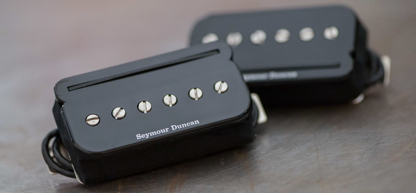
i am again reconfiguring my HS Guitar. Installed is a Häussel single coil with 2 wires and a Seymour Duncan P Rails.
I only have a volume pot and a blade switch and was wondering if i could realize this wiring with a tele 4 way switch:
1. humbucker series
2. humbucker parallel
3. humbucker split coil (outer coil, the p90 side)
4. neck sc
2 and 3 could be in a different order, 1 and 4 must be like that.
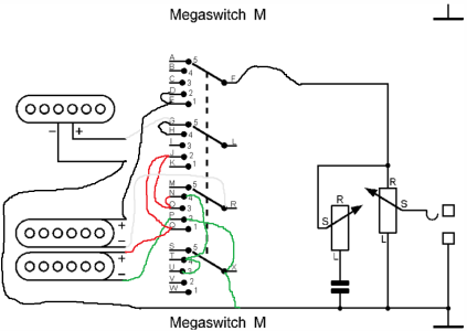
alternatively if the 4 way is not possible, i could also live with a 5 way solution. i have available also the eyb megaswitch e, the standard fender 5 way, the schaller p and the schaller m megaswitch.
i would love to avoid any further controls such and use only the blade. nearly all diagrams i find miss the parallel hb option (except for the schaller p, which misses sc options and splitting). the only diagram i found was for the dimarzio dp1112 which will probably not fit my telecaster control panel and which is also not available.
did one of you try something similar and do you think that this is possible with my existing material?
thanks in advance
j.
i am again reconfiguring my HS Guitar. Installed is a Häussel single coil with 2 wires and a Seymour Duncan P Rails.
I only have a volume pot and a blade switch and was wondering if i could realize this wiring with a tele 4 way switch:
1. humbucker series
2. humbucker parallel
3. humbucker split coil (outer coil, the p90 side)
4. neck sc
2 and 3 could be in a different order, 1 and 4 must be like that.
alternatively if the 4 way is not possible, i could also live with a 5 way solution. i have available also the eyb megaswitch e, the standard fender 5 way, the schaller p and the schaller m megaswitch.
i would love to avoid any further controls such and use only the blade. nearly all diagrams i find miss the parallel hb option (except for the schaller p, which misses sc options and splitting). the only diagram i found was for the dimarzio dp1112 which will probably not fit my telecaster control panel and which is also not available.
did one of you try something similar and do you think that this is possible with my existing material?
thanks in advance
j.