Building my own live mixer

mayfly

Epic Member
Messages
8,692
Hi folks,

Because of my never ending quest for excellence, and also because I'm completely insane,  I've decided to try my hand at building my own live music mixer, specifically designed for my band Cornflower Blue.  Yep, instead of being happy with a $100 mixer from Behringer, I thought I could do better.

So I set about thinking what the ideal mixer would look like.  I figured it would have to be small, only include the channels I actually needed, be in it's own road case, and have excellent sound quality. 

When it came to features, I departed pretty early from conventional wisdom!  EQ?  Who the hell needs that!  A bunch of knobs that I'll always need to make sure are never on!  If you don't have good tone at the source, fix it!  Maybe a 80Hz low cut on mic inputs, but that's it!  Speaking of mic inputs, when was the last time you used a condenser mic live??? Forget the phantom power!  Who needs it!!  Now compression on the mics - that's something that I would use!  It would be great to have an instrument input that I could actually plug a violin directly into and not have it crap out.  10K input?  100K?  forget it!  I need at least 1M into a FET Style front end for that.  A stereo input for electric drums and an iPod.  A couple of line level inputs for guitars, but with mute switches for when Theresa leans her guitar against a monitor and wonders why it's feeding back.  Oh - and it has to look cool. And be small. and drive line level into long cables. and ... and...

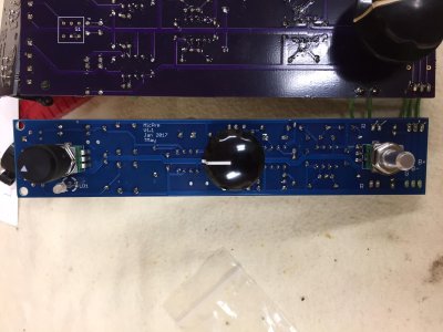
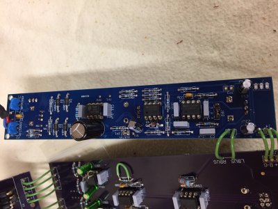
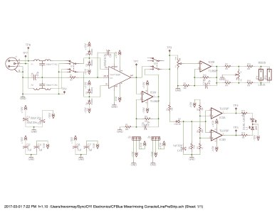
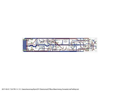
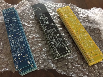
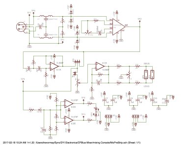
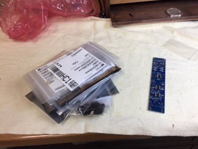
All this led me into a fairly long design phase.  I did my research, did some test circuits, fired up good old Eagle Cad, layed out some boards, and sent them to dirty PCB for fabing just after Chinese new year.  I just got them back today:

index.php


The blue boards are mic pre strips, the yellow ones are line level input strips, and the black ones are compressor side chains for the mic pres.  More to come on the actual designs, the build, and how things sound.
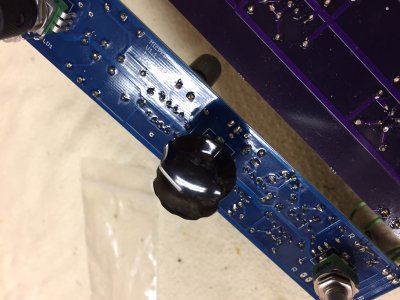
 

Attachments

  • IMG_3566.JPG
    IMG_3566.JPG
    988.3 KB · Views: 799
I occasionally have bouts of "I can melt down the play sand in the kiddo's sandbox and make my own semiconductors" too but ....
you sir are sick. Get help.
 
Well, I for one think it's a good idea. You get what you want the way you want it, and don't have to pay for what you don't like/want/need. How many mixers are there in the back of the house with 82 bajillion knobs and buttons and esoteric capabilities, the vast majority of which are never used but fully capable of screwing up an otherwise perfectly good sound that only needs to be mixed down and amplified? I submit that it's nearly all of them. The "one size fits all" design paradigm is primarily good for achieving economies of scale, not suitability to task. Although, to be fair, it looks impressive  :laughing7:

Of course, not everybody can design/build a mixer, and even if they could there's always the time issue. It's not a trivial task. So, you take advantage of those economies of scale and buy the mass-produced product so you can have something that will do what you need RFN while ignoring all the parts you don't need as best you can.

I think there's also the beauty of a concise, well-executed electronic design that maybe only an engineer can appreciate. A clever circuit, a redundancy a manufacturer would never use due to cost that could save the day in real life, a simplification that makes the thing faster or more accessible, etc.

So, good for you, Trevor! I wish you all the best, and look forward to seeing the end result. Be sure to keep us up on the details  :icon_thumright:
 
Looks awesome, this is one of the things I hope to be maybe able to do after completing my engineering degree in 4 years time. All that stuff I can make  :toothy10:
 
I think it looks absolutely awesome.

Who knows, you might end up doing this as your primary job somewhere down the line ... :icon_thumright:
In five, ten years time, we'll be watching Youtube clips from NAMM of you standing in a giant booth showing the latest line of custom mixers.
 
Excellent idea.
I'd suggest an advanced parametric EQ section with 2 sweepable mids (hi mid and low mids) Hi centered at 10,000 , lows centered at 100, or for that mater why not sweepable lows and hi also.

Yea. 4 band parametric. hi pass switch. OK well, might as well put a Q knob on all 4 bands.

 
Thanks everyone!  Very funny Steve.

Here's the schematic for the Mic Pres!  The first bit after the connector is some EMI and ESD protection.  Removing phantom power got rid of a whole pile of resistors, diodes, and <shudder> electrolytic caps in the signal path.  This all goes into a THAT Corp mic preamp chip.  THAT corp is pretty interesting in that they essentially create high quality discrete transistor circuits, tune them, make them thermally stable, then put them into an IC package.  They are used in a lot of big name gear like Trident and Grace Design.  It's good stuff.

From there it goes into a Linkwitz Riley 12db/octave 80Hz HPF (with a jumper to take it out if I don't like it), and another jumper to take it in/out of the compressor sidechain.  Then it's into the volume control, some gain, the pan pot and connectors to the left/right summing buses, which is how the individual boards are linked together.  The stuff at the bottom left is a signal present / overload circuit.  One diode that is green with signal and orange during overload.  The rest of it is decoupling caps that I sprinkled liberally over the whole thing.  Oh - and it's a +/-15V design.

index.php
 

Attachments

  • MicPreStrip.jpg
    MicPreStrip.jpg
    639.4 KB · Views: 556
Here's the resulting 2 layer board layout.  It was a lot of work getting it this far!

index.php
 

Attachments

  • MicPreStripLayout.jpg
    MicPreStripLayout.jpg
    670.2 KB · Views: 579
This is really interesting. I'm not too familiar with that level of electronics but I appreciate the effort you're putting into it.
 
This is the coolest thing ever! I wish you luck and will be watching with far too much enthusiasm.  I only ever seem to want to do projects that are insane.
 
A bundle of parts just arrived from Mouser.  One bare board, a bag of parts, and a soldering iron.

index.php


Let's have at it!
 

Attachments

  • bareboard.jpg
    bareboard.jpg
    519.8 KB · Views: 517
Some quality time with a soldering iron and all the parts are in.  Electronics are on one side, and "the user interface" (pots and LEDs) are on the other.  I did it this way to allow for parts that are higher than the potentiometers - caps in particular.  The jack is remote mounted so I have the ability to put it whereever.  The purple board is a prototype summing mixer that I previously made; re-doing that board is likely next on the list of things to do.

The knobs are inspired by an old RCA radio desk that I used in high school.  Yep, we had our own AM radio station - CKJP :).  It was cool to annoy the jocks by blasting the entire first side of 2112 over lunch.  But the desk was spectacular!  it sounded great and had those fantastic knobs.  So, those are the knobs that I'm using!

index.php


index.php


index.php
 

Attachments

  • top.jpg
    top.jpg
    188.3 KB · Views: 526
  • bottom.jpg
    bottom.jpg
    571.7 KB · Views: 515
  • knob.jpg
    knob.jpg
    543.9 KB · Views: 487
So normally when you've got a board like this together for the first time you follow a bring up process.  You apply power (current limited) and check the rails to ensure there are no shorts.  Then you apply a test signal and test out the functionality of each section.  For example, does that HPF actually do what I think it should?  that kind of stuff.  Lots of looking at the scope.  Then you see what the performance envelope of the system is by running it from DC to daylight.  This circuit should go to 100KHz for example, but it's bandwidth limited above that.  Shouldn't pass RF because my radio days are over  :)

So yea, you could do all that, or you could just plug in a microphone, attach an amp/speaker on the back end and do a hail mary and see what it does!  That's what I did.  Turns out that the thing works!  :headbang:  Still need to go back and characterize it  mind you, but I can sing loud and clear through it.  Even the signal / overload LED works as expected.  It's pretty cool.
 
Awesome. Looking spectacular.
Congrats to it working as you planned. Must be a great feeling.

Now you only have to solder a few more channelstrips and hook them up too and put everything in a nice box.

Next stop: NAMM :icon_thumright:
 
Yeah, to hell with all that tip-toeing around. Power it up and see if it can hold its smoke!

Congrats on a successful test!
 
This is so damn cool. Very impressive looking board. I agree on the knobs, too. They just reek of vintage electronics. Congrats on the successful test.
 
Nice going, I'm impressed! Worked first time, that don't happen very often......  :hello2:
 
With the mic pre out of the way, time to work on the Line Pre.

This one is designed with balanced inputs (XLR or TRS - I used one of those agnostic jacks), and a switchable gain stage to take it from +10b levels to -4db levels.  and I put in a mute switch :)
I relied on the THAT balanced receiver chip as I didn't want to mess with matching resistors and all that you need to do to get the textbook balanced receiver circuit working.  The volume control, gain, pan pot and overload detector circuit are the same as the mic pre.  Unless I've done something really stupid, this one should just light up as well.  There!  I've just jinxed it!

here's the schematic:

index.php


And here's the PCB layout:

index.php
 

Attachments

  • LinePreStrip.jpg
    LinePreStrip.jpg
    600 KB · Views: 396
  • LinePreStripLayout.jpg
    LinePreStripLayout.jpg
    516.9 KB · Views: 429
Back
Top