Series/Split/Parallel Wiring with 8 Pin DP3T Switch

Saaif88

Newbie
Messages
4
Hey Everyone,

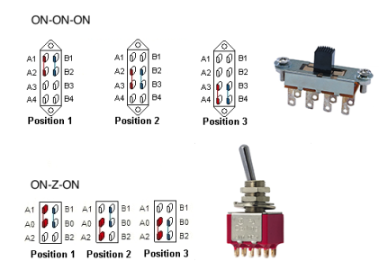
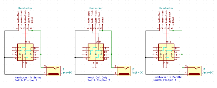
I'm trying to wire up a Humbucker in Series/Split/Parallel. There are plenty of wiring diagrams out there for this, but they all use a very specific 6 pin ON/ON/ON switch.

I'm trying to use a very low profile slide switch instead of the normal "Bat Handle" style switch, and unfortunately, I cannot find a single switch like that which exists in the 6 pin variety. They are all 8 pins, without the "Z" style middle position.

Can anyone point me in the right direction for how to wire this? I tried figuring it out myself, but I can't visualize a way to do it. If anyone knows of a slide switch that is wired like the normal guitar switches, that would work too.

Thanks in advance!
 

Attachments

  • Switch Comparison copy.png
    Switch Comparison copy.png
    59.8 KB · Views: 72
Hi Welcome to the forum.

On the 8 pin shown solder some jumpers on the centre position lugs.

1. Between A2 and A3
2. Between B2 and B3

Then you have what is effectively the same as a 6 pin switch.

The 8 pin centre could also be wired instead with jumpers.

1. Between A2 and B3
2. Between B2 and A3

That would give you a different layout between the other poles and switch throw. But either of those should be the key to adapt a 6 pole wiring for differing on/on/on switches to this type of switch.

 
Hey Stratamania,

Thanks so much for the reply, I appreciate it! I'm still not entirely sure how to wire it if I bridge the two middle contacts. The problem is that I can't see a way to replicate the "Z" contact style. If I try to replicate that on the 8 pin switch, it doesn't really work...

It might be asking too much, but could you make a rough wiring diagram? It might very well be possible to wire it up by using the 8 pin switch, but I don't even know where to start the wiring. I'm generally pretty good with this stuff, but I find it difficult to visualize this switch in this application...
 
Okay, so I sat around for far too long and tried to make this work, but I couldn't find a way to do it with a DP3T switch. Maybe I'm missing something extremely obvious, but I just couldn't visualize it. That being said, I think I managed to figure out how to do it with a 3P3T Switch, which actually has 12 pins.

I have attached my current wiring for it. It seems like a lot of it is wasted, but it seems to fulfill my needs, which is to have a Series/Split/Parallel switch. I ended up using the North coil as the split coil, but this can easily be modified to use the South coil instead. I'm not entirely sure it makes any real difference, but if it does, please let me know! If the schematic is wrong or doesn't make sense, please let me know! I will actually buy one of these switches and give it a shot when I can.
 

Attachments

  • Series-Split-Parallel Wiring.PNG
    Series-Split-Parallel Wiring.PNG
    19.9 KB · Views: 74
Per my last post - apologies I missed something regarding the internal jumpers of the switch so what I suggested would actually not work.

Per your 3P3T 12 pin switch - if it fulfills your needs it is not really wasted even if you have some pins left over.  I cannot see from the diagrams the basic switching of the switch itself to compare the diagrams against.

If your north coil is a screw coil and the south a slug coil normally when split the south coil is left as the active coil. Though some do split to the other coil, the main difference it might make all things being equal is the coil closer to the bridge is more likely to give a slightly brighter output than the other due to its location.
 
The internal switch contacts are present on the diagram, but they are a bit hard to see, my apologies. The "brown" coloured "wires" on the diagram represent the internal connections, whereas the blue wires represent the external jumpers that need to be added.

This seems to be the standard contact layout for a 3P3T switch, and the specific switch I found is from CW Industries. I've attached a PDF of their slide switch schematics, and they refer to it as a 3P/3POS switch. From the datasheet, the schematic is:

POS A = 1&2, 5&6, 9&10
POS B = 2&3, 6&7, 10&11
POS C = 3&4, 7&8, 11&12

I'm actually not using this with a traditional Humbucker, I'm using this with a Little 59', which is a humbucker in the footprint of a single coil, and in this case, both coils have what looks like screws on them. I might just try it out and see if it makes a difference, but I don't imagine it does, since the coils are so close together in this case.

Thanks for all of your help once again! I really appreciate it!
 

Attachments

  • SLIDE_SWITCH_SCHEMATIC.PDF
    630.2 KB · Views: 32
If you are using a Little 59 (which I am familiar with) you may find that in the end there is not a lot of point in doing a series/split/parallel switch. Perhaps a choice of series for normal use and a switch to parallel would be more usable?

Per your last diagram, you have the black wire going to ground of the output jack and green and bare to hot, it should be the other way around. Which will also throw out the rest of the diagram.

Is this just one pickup and one switch in total?
 
@Saaif88

Here is a link to a later thread where there is a solution to a similar question.

 
Back
Top