Leaderboard

I need help understanding this diagram!

I had this kind of trouble before with a 5-way super switch when I installed it with s/c mounting screws that were too long. Two of the common terminals of the super switch were directly inline with the mounting screws. In this case the longer screws came in contact with the common lugs so they were permanently grounded. However i test for this kind issue, so it wasn’t a major drama.
 
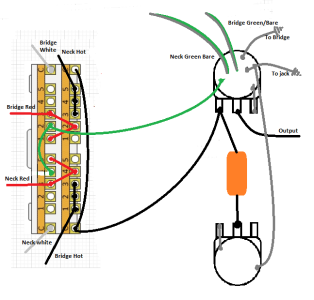
Alright, I have searched high and low and finally sound the wiring diagram I think I need. The idea is HH wiring with a 5 way four pole super switch to do the following: bridge series, bridge parallel, bridge and neck in parallel, neck parallel, neck series.

I wired this up as best I could, two things I had questions about. One is, does the orientation of the super switch matter? It happens to be that the orientation of my switch has to be opposite to the diagram to fit because the route and position charvel decided to place it. Two, I’m not sure I understand the connection points. It seems to me there is tons of jumping going on, but there are some that have black dots and some that don’t. What’s the relevance of this. I’ve wired every guitar myself prior to this with no problem understanding, this is just a difficult one for me. Plus I’m completely uneducated about the process. I just follow diagrams.

Any help would be greatly appreciated!
I see that you ended up using Stratamania's diagram instead of this one which comes from GuitarElectronics.com, but for anyone that's interested in the earlier question of what the added green lines are doing, that was someone's alteration to make both humbuckers in Position 3 wired to be In Parallel instead of In Series. For each humbucker to be wired In Series in Position 3, there would be a wire connecting the two Lug 3s on adjacent poles like you see depicted in Postion 1 / Lug 1s.

Stratamania's diagram is definitely an improved design of how to get the same results with less wiring. Nice job Stratamania.
 
Here is a screenshot from my bumper fun book of wiring. @JoshuaB you are in luck that I happened to have this already drawn out.

View attachment 61783

I have a question about this diagram.

Correct me if I'm wrong please, but in theory one could connect the leg 2 of the lower left pole to the leg number 4 of the lower right pole, and this could be connected to the same pot case the green and bare cables of each pickups are??

I made a schematic explaining what I mean.


Is this correct?
 

Attachments

  • HH 5way.png
    HH 5way.png
    86.8 KB · Views: 4
I have a question about this diagram.

Correct me if I'm wrong please, but in theory one could connect the leg 2 of the lower left pole to the leg number 4 of the lower right pole, and this could be connected to the same pot case the green and bare cables of each pickups are??

I made a schematic explaining what I mean.


Is this correct?

In theory, you could for this wiring as electrically both the bridge and neck green and bare connect to a common ground.

However, if you refer to my diagram, the reason the green and bare of both pickups go to the respective switch terminal is also for physical wiring practicality. That way you have the wires from the pickups all connected to the switch, meaning they are not as spread out. You then only need to connect those wires to a common ground such as a jumper between the poles as you have shown and then one to the back of a pot or other common ground.
 
Back
Top