HSH with 2p4t switch on each H

Krasson

Newbie
Messages
5
Hi everyone,

I need some help as I am painfully new to guitar wiring and have a very ambitious project. Is there anybody that can check my diagram and tell if it is correct or if there are mistakes or if the whole thing is just ridiculous?

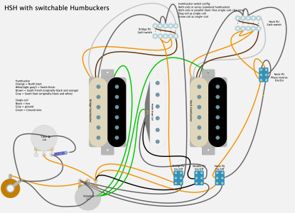
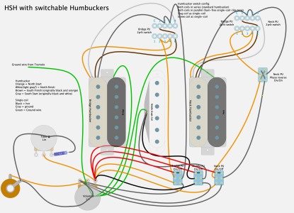
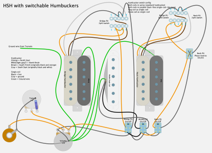
I'd like to wire up the 3 pickups so that each Humbucker pickup is switchable as follows:

Humbucker series
Humbucker parallel
North coil
South coil

The bridge pickup will then be switchable to reverse the polarity

Then I'd like each pickup to get an on off switch for which I am using DPDT switches. After that the Volume and Tone knobs will be connected.

I tried to match the color coding to my lace sensor finger burners:

Humbucker
Orange = North Start
White = North finish
Brown = South Finish (originally black and orange)
Gray = South Start (originally black and white)

Single coil
Black = hot
Gray = ground
Green = Ground wire

I copied the wiring diagram for the Humbucker switches from this website: https://www.premierguitar.com/diy/mod-garage/triple-shot-humbucker

I'l be glad about anything you can tell me.

Cheers


Attachments

  • Greeny.png
    Greeny.png
    451 KB · Views: 45
Wowzers! Too much for my small brain. Will you be able to remember what is what while your playing?!!
 
May I be bold and ask, are all these positions you mention that so different that your audience will know the difference?

I mean N vs S pole on the split.  Chose 1. I opt to split HBs (when they are worth splitting which is less than 35% of the time) to the far coil.  My exceptions are for situations with a 24 fret neck. The inner coils are now close enough to emulate Strat quack.
 
Two most obvious issues I can see:
1) The middle lug of the volume control is not connected.
2) There is no permanent grounding of the humbuckers as all 5 wires are connected via 2-pole switching.

 
JohnnyHardtail said:
Two most obvious issues I can see:
1) The middle lug of the volume control is not connected.
2) There is no permanent grounding of the humbuckers as all 5 wires are connected via 2-pole switching.

To expand a little on this.

1. The volume and tone pot wiring needs revisiting. The middle lug of the volume pot is where the hot output wire needs to be connected to the hot of the output jack. The lug where this wire is currently connected needs to be grounded usually by bending it over and soldering it to the back of the pot.

2.The humbucker grounds/shields must be connected directly to ground often again to the back of a pot. This means the ground is independent of the switching.

3. The volume pot also has its input lug wired to ground and the output jack wiring has tip and ring also mixed up.

4. The green ground wire of the single coil as described also needs to attach to ground similar to point 2. but is not shown. This is assuming the grey wire is negative and the orange is plus for the single coil of which the type of pickup is not mentioned.

This is without looking yet at the switching which due to the above is also thrown out as to its intent.

Also label the diagram, which pickup is bridge, middle, neck, which switch is which etc? Put a colour code on the diagram itself.
 
Spud said:
Wowzers! Too much for my small brain. Will you be able to remember what is what while your playing?!!

I’m not sure. 😅 This is not necessarily supposed to be for live. I want something to experiment with and the more options I have without having to buy tons of guitars the better.
 
stratamania said:
JohnnyHardtail said:
Two most obvious issues I can see:
1) The middle lug of the volume control is not connected.
2) There is no permanent grounding of the humbuckers as all 5 wires are connected via 2-pole switching.

To expand a little on this.

1. The volume and tone pot wiring needs revisiting. The middle lug of the volume pot is where the hot output wire needs to be connected to the hot of the output jack. The lug where this wire is currently connected needs to be grounded usually by bending it over and soldering it to the back of the pot.

2.The humbucker grounds/shields must be connected directly to ground often again to the back of a pot. This means the ground is independent of the switching.

3. The volume pot also has its input lug wired to ground and the output jack wiring has tip and ring also mixed up.

4. The green ground wire of the single coil as described also needs to attach to ground similar to point 2. but is not shown. This is assuming the grey wire is negative and the orange is plus for the single coil of which the type of pickup is not mentioned.

This is without looking yet at the switching which due to the above is also thrown out as to its intent.

Also label the diagram, which pickup is bridge, middle, neck, which switch is which etc? Put a colour code on the diagram itself.

Thanks a lot for the pointers!!!

Point 3: The output jack is labelled T and S which I assumed is Tip and Sleeve. Am I wrong?

I've updated the diagram. What do you think?
 

Attachments

  • Greeny.png
    Greeny.png
    599.7 KB · Views: 37
Seems to be heading into a reasonable direction...

The diagram is a little unconventional so not too easy to read for my older eyes. T  & S is Tip and Sleeve.

The 4TDP switches which ones are you using as the Premier article uses a rotary switch, at first your diagram looked like common was joining to common but I assume it is meant to be common to 1 of the opposite pole.

It might be an idea for your on off switches to jumper the positive and negative output terminals together and then join one of each of these to the volume pot.

In terms of the bridge out of phase or reverse polarity  as mentioned in the first post "The bridge pickup will then be switchable to reverse the polarity" this shows as wired to the neck pickup. With both humbuckers on with each in series, whether the bridge or neck polarity is reversed it will give a similar result. Also in terms of constructive feedback your diagram has the wires going to the side of this switch rather than its terminals.

Overall it may work but not be too practical in usage however.

Perhaps check out also a Freeway 5B5-02 Model switch if you are not aware of them.
 
I like your updated diagram and the added text makes it easier to understand.

I noticed a problem with the tone control being grounded in two places.    The grounding of the tone control case and the link from the case to the capacitor are both correct.    However you should remove the ground connection on the lug of the tone control, as that lug should only be connected to the tone capacitor.
 
I'm using a program called DIYLC. I don't think it's made for this kind of application but it has some guitar components.

You were right to assume common was connected to common because that is how the switch is set up that I got. They only just arrived and I wasn't sure how they were set up. It should be modelled correctly now.

Do I connect the jumpered output from the on/off switches to the lug of the volume pot? As I did in the Diagram? The wires for that are the red ones.

The switch for reversing the phase is still just a concept. On which PU it ultimately goes is a matter of the final layout and that depends on the scratch plate which I haven't made yet. Same as the cable layout. They're all over the place right now.

In terms of practicality I know it might be a bit much but right now it's fun to build it like this. My next project will be a little more basic depending on what I learn through this one.

Anyway, you guys are legends!

Thanks
 

Attachments

  • Greeny.png
    Greeny.png
    663.1 KB · Views: 35
No you do not need the red wires. What I mean is instead of taking two orange wires and a black wire to the volume pot take a jumper from one switch to the other for those wires and then take one wire to the volume pot instead of three. And a similar arrangement for the - wires from the switches and then to ground.


Right... I think I get it.

Do I need connect the unused poles of the on/off switches like I did or is that irrelevant?
 

Attachments

  • Greeny.png
    Greeny.png
    607.7 KB · Views: 37
That's it.

The unused parts of the switch don't need to connect together, though it is not really going to do anything if they are.
 
Last edited:
Back
Top