DP3T Series/Switch/Parallel?

PunchlineChar

Newbie
Messages
9
Hello everyone,

I've got some mods I'm fixing to do to my strat build, and was looking for clarity on some of the wiring. It's going to have a Duncan 78 in the bridge, and I'd like to have a series/split/parallel switch. I'm wanting to use a slider switch though, like this Switchcraft: https://www.stewmac.com/electronics/components-and-parts/switches/switchcraft-slide-switches/

Thing is, it's a DP3T and not a DPDT which is what every diagram I can find is for. Could someone tell me if it's possible to wire this up? Would it just be a matter of placing the wires differently along the switch or would I have to use some creative jumpering? If it's not possible I might just use the 2 way version and make it a split switch but I'd like to have more sounds to play with.

Any help is appreciated!
 
With that type of switch, I do not consider that it is possible, even with jumpers you just run into logical conundrums.

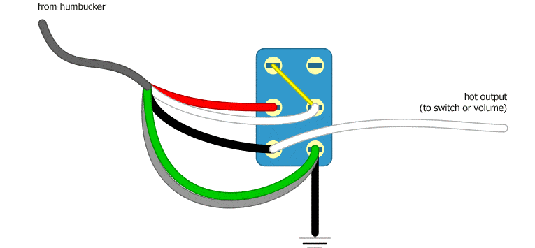
However, you could do it with a toggle switch per the below link. So unless you can find a slider switch that does the same thing which is doubtful, you are out of luck, I think.


I am happy if someone else is able to show something to the contrary for that slider switch.
 
This is the closest I was able to get to the wiring with this switch, which popped into my head after walking away from the riddle. So in some way I am contradicting myself :)

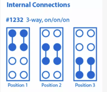
Here is a screen grab from the diagram on Stewmac of the internal connections.

1665631457408.png


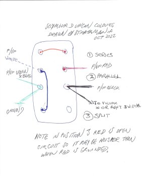
And here is what I came up with...(quick hand drawn sketch as it popped into my head during the night)

sliderwiring.jpg


Explanation of what is happening.

Seymour Duncan wiring colours.

Green and Bare connect to the shown switch terminal and in turn to a common ground such as the back of a pot.
Black connects to the shown switch terminal and in turn either a selector switch or direct to the volume pot input lug if only using one pickup.
These wires are always in circuit, which is what we want.

  1. In position 1 Series: the jumper wire shown in red with the internal switch connections joins the red and white wires together to form the series link.
  2. In position 2 Parallel: red is connected to black, and also white is connected to the green and bare terminal via the internal switch connections to give us parallel.
  3. Position 3 Split: White is connected via the blue jumper and the internal switch connection to the green and bare terminal and to ground.
Note and caveat on position 3: the north coil via black and white is active, which is what would be achieved by normally shunting the red and white to ground (see linked article for toggle switch in last post) however with this slider switch red of the other coil is left open circuit which is not my preference so whilst you will get the split coil this may result in some circumstances noise. (the open circuit is still grounded via white at the other end of the coil) A split coil is not hum cancelling on its own in any event so you may get noise in any case even with a circuit that grounds both red and white for the split, which is not possible here.

Give it a try and if it works for your needs, great.
 
Last edited:
I really appreciate you putting it in all this effort for this, thank you! I'll get back to you whenever I have a chance to wire it up. My guitar is shielded so hopefully that'll help with the noise.
 
OK, let us know how you get on. It may or may not create any extra noise dependent on environment etc, but I mention it just as a caveat just in case.
 
I'm about to try exactly the same - I'm making a thin-ish bodied electric mandola & trying to avoid toggle-switches, prefer slider switches. I will try out your diagram - except I'm using Irongear's "Jailhouse Rails" (x 2) so the colouring will be different. It would be interesting to hear whether your suggestion (drawing) worked for PunchlineChar? It'll be a month or so before I will get down to wiring anyway. Thanks for the forum.
 
@Flatback welcome to the forum, if you use this wiring let us know how you got on. The OP of this thread has not been active on the forum since December of last year and has provided no feedback for the help given regarding actual wiring unless he has not wired it up yet.
 
Last edited:
Back
Top