You are using an out of date browser. It may not display this or other websites correctly.
You should upgrade or use an alternative browser.
You should upgrade or use an alternative browser.
Some Vintage Test Gear Madness
- Thread starter mayfly
- Start date
mayfly
Epic Member
- Messages
- 9,197
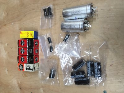
Just got a package from AES for the signal generator re-build. Check out those NOS tubes, with the exception of the JJ 12AT7. Interestingly, the old tubes were under $10.00 each. Cheaper than the JJ!!
For the signal caps I splurged on Solen. The can caps are the shockingly expensive CE Manufacturing caps. Everything else is good old IC.

For the signal caps I splurged on Solen. The can caps are the shockingly expensive CE Manufacturing caps. Everything else is good old IC.
Attachments
mayfly
Epic Member
- Messages
- 9,197
Cagey said:Wow. Really gonna make that baby sing, eh?
Sure - but only one note at a time
mayfly
Epic Member
- Messages
- 9,197
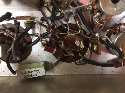
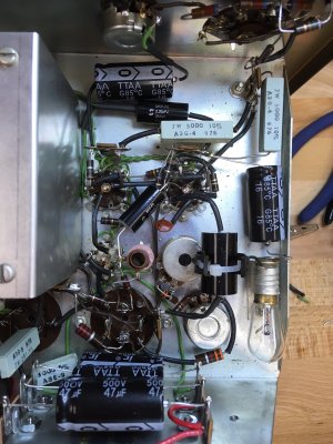
Starting on the decoupling caps in the power supply.
Old vs New

ok - I sure hope I remember how this all goes back together!!

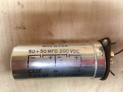
A strange ass cap for power supply bootstrapping. No replacement available - so I'll build something using regular caps (I've already a plan in hand)

Old vs New
ok - I sure hope I remember how this all goes back together!!
A strange ass cap for power supply bootstrapping. No replacement available - so I'll build something using regular caps (I've already a plan in hand)
Attachments
mayfly
Epic Member
- Messages
- 9,197
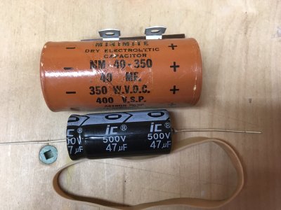
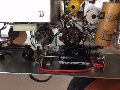
Here's my plan for that bootstrap can cap - a couple of 47uf caps on terminal strips. The third cap was another decoupling cap that the original design just had hanging in space. ok, there was some *tape* residue on the chassis left over from holding the cap in place - but I figure this is much safer 

I fired it all backup after doing these mods and the power supply is working fine <phew!>. Unit is still working as it was as well. That is, working good on anything higher that 2KHz and not so much on anything less
I have a theory that the caps in the feedback section of the tuned oscillator are leaking which is screwing up things. We'll see if things improve as I replace them.
Attachments
Cagey
Mythical Status
- Messages
- 24,425
It may be just the angle of view, but it seems like the high voltage side of those caps is awfully close to the mounting lugs for those terminal strips, which are tied to the chassis, which I assume is also ground. I wonder if it would be worth it to find a way to isolate those mounts?
Otherwise, looking good so far.
Otherwise, looking good so far.
rgand
Epic Member
- Messages
- 5,934
You can count me in on this. It's an area I never learned anything about and it's fascinating.Logrinn said:I'm extremely impressed by your eletrical knowledge/know-how.ccasion14:
This is very enjoyable to follow.
mayfly
Epic Member
- Messages
- 9,197
Cagey said:It may be just the angle of view, but it seems like the high voltage side of those caps is awfully close to the mounting lugs for those terminal strips, which are tied to the chassis, which I assume is also ground. I wonder if it would be worth it to find a way to isolate those mounts?
Otherwise, looking good so far.
The terminal strips that I mounted? It's just the angle - the terminals are completely different from the mounting points and have good isolation.
mayfly
Epic Member
- Messages
- 9,197
Rgand said:You can count me in on this. It's an area I never learned anything about and it's fascinating.Logrinn said:I'm extremely impressed by your eletrical knowledge/know-how.ccasion14:
This is very enjoyable to follow.
Thanks gentlemen! But all I'm really doing is replacing worn out parts.
mayfly
Epic Member
- Messages
- 9,197
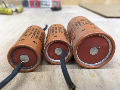
ok, all caps have been swapped. Here's a little sample of the dead solders:

Note that each has the tell-tale bump that says "I'm dried out and about to spray my internals all over the inside of this thing". I'm glad I replaced them.
Here's the thing though: The unit still runs like it did before. No change to the waveform at all. Time for Occam's Razor: The simplest explanation is likely the correct one: Tubes! Tubes in old tube equipment might bad. I'm going to do a hail mary and replace them all with the NOS units that I bought. Here goes.
Attachments
mayfly
Epic Member
- Messages
- 9,197
Well Crap! That was easy!
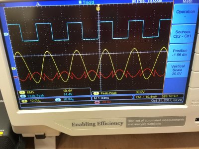
Unit is now running low down. Here it is at 500Hz: Waveforms look nice and clean!

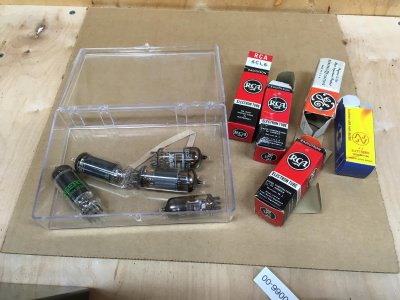
Here's the original tubes that were in there, along with the boxes of the NOS replacements.

Here's how things look running up to daylight (well, 1MHz in our case )
)

I think it's time to do another calibration run then declare victory!
Unit is now running low down. Here it is at 500Hz: Waveforms look nice and clean!
Here's the original tubes that were in there, along with the boxes of the NOS replacements.
Here's how things look running up to daylight (well, 1MHz in our case
I think it's time to do another calibration run then declare victory!


