Replacing Toggle Switch pup selector with DPDT on/on/on Mini Switch

alexreinhold

Senior Member
Messages
678
Hi all, I have a wiring question and need help. Thanks so much in advance!

I want to a 2 humbucker - 1 volume - 1 tone (push/pull coil split) - 3 way switch setup.

However, instead of using a standard Switchcraft toggle switch, I want to use a Göldo EL013 on/on/on mini switch (dpdt). How would I have to adjust the wiring?

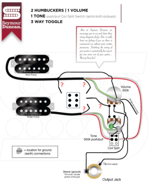
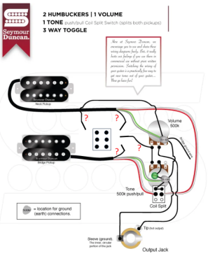
Original:
AGV_vUe9kVA1PMbUdh-vhoqmSOk0cvhs1XFYSQiAdwO0rbEZ9oTgUDtzUK8nXCKxNUNABOjHlwboCfCXS-cX-Onxsfczb5x-nYU-dYV_TzcZNFtYAke7J-tSPHngKT4cEOJ9_vwS335DUEWh5MwqykLUw69_6f2pf0iX=s2048


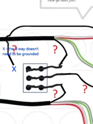
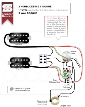
Adjusted:
1717921408370.png
Bonus question:

where is up and down on this thing?
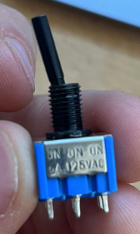
1717921488578.png 1717921506265.png
 
Bonus question:
where is up and down on this thing?
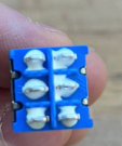
1717921488578.png
From what I can tell from the mini switches I have, if the switch is like in the picture (with the lever pointing to the left), the active poles would be the ones on the right. Basically, the active poles are the opposite of whichever position the lever is in, if that makes sense. At least, that’s the way mine work. I’m assuming they are all the same simple switch.
 
From what I can tell from the mini switches I have, if the switch is like in the picture (with the lever pointing to the left), the active poles would be the ones on the right. Basically, the active poles are the opposite of whichever position the lever is in, if that makes sense. At least, that’s the way mine work. I’m assuming they are all the same simple switch.
Vernschrock is correct. So OP, it doesn't matter which orientation you wire the switch, just keep in mind that the "throw shaft" 's position correlates to the opposite side of the switch, as Vernschrock said. That really only matters when you're at near the end of the project and physically installing the switch and you want to be conscientious about how you want the throw direction to work for you (down = bridge only and up = neck only, or vice versa).
 
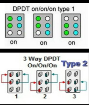
And for how to wire that 3 way on-on-on, first review this Pic that explains which of the 6 poles are active in each of the three positions.

[Edit: replaced the original pic that only showed a Type 1 switch, with a pic that shows both Type 1 and Type 2 switches.]

Picsart_22-12-13_23-57-58-470.jpg
 
Last edited:
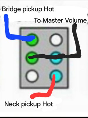
... And then see this pic of where to connect/solder the wires.

** the wire colors shown here are generic. You'll need to lookup online the wiring color code uses by the manufacturer of the particular pickups that you want to use.


3way on-on-on - wired as 3way pup selector.jpg

edit: per @stratamania 's request below, I'm re-attaching an earlier diagram that i had replaced. It only works if you know whether you have a Type 1 vs Type 2 switch AND you have it physically oriented correctly when wiring it. (Using the continuity test on a multimeter is how you determine this.) Whereas the diagram above in this same post will work regardless of whether the switch is a Type 1 or 2.
3way on-on-on schematic.jpg
 
Last edited:
There are two types of 3 way on on on toggles a type 1 and type 2.

Effectively, the difference is when the switch is in the middle, which of the outer terminals are connected internally.

The diagram @Floyd_Argus has posted inline in the post will work in either case.

The other diagram he has as an attachment, which is below, may work for one type and not for the other. If it did not work, you would move the blue wire to the terminal to its right and the red wire to the terminal to its left.

20751-3aac066f422df92d3e626c41ee72ef09.jpg
 
Yes, thanks Stratamania. I spotted a little later on my own how the wiring diagram I provided originally needed a fix (i.e. extend the two pickup hot wires to the next pole over) to cover if the switch is type 1 or 2. I updated that diagram in my earlier post, but forgot to delete the old diagram which was still there as an attachement. I've also gone back and deleted that attachment now.
 
Last edited:
@Floyd_Argus and @stratamania thank you so much for the helpful input. As stratamania knows, my electronics knowledge is very limited. Hence, the followzing stupid question:
can I use the diagram below as a blueprint?
--> i.e. is the rest of the wiring still OK?
--> and if yes, where would I go with the lose ends of the wires next to the red question marks?
1718023390606.png
Apologies for my stupidity :-/
 
@Floyd_Argus and @stratamania thank you so much for the helpful input. As stratamania knows, my electronics knowledge is very limited. Hence, the followzing stupid question:
can I use the diagram below as a blueprint?
--> i.e. is the rest of the wiring still OK?
--> and if yes, where would I go with the lose ends of the wires next to the red question marks?
View attachment 62173
Apologies for my stupidity :-/

Alex,

You haven't told us what Brand of pickups you will be using. Each Brand uses their own pickup wiring color code scheme. If the two pickups you are using are not Seymour Duncan pickups, then you'll first need to convert the colors shown in the wiring diagram to the wire colors of the brand you are using.

You should be able to find on the website of the Brand you are using, the info about what wire color scheme they use for their pickups.

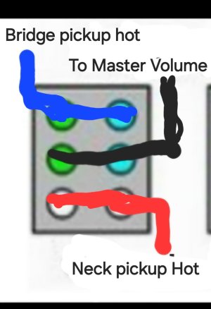
Following is how the 3 way switch should get wired, assuming Seymour Duncan wire color coding scheme.

Screenshot_20240610_144311_DuckDuckGo.jpg

Remember earlier comments from myself and vernschrock about how it doesn't matter whether you connect Neck pickup hot wire to the top two lugs or Bridge pickup hot wire to the top two lugs, and same thing for bottom two lugs. But it does matter which way you physically orient the switch into the guitar later at the time of install.
 
@alexreinhold if you are using Seymour Duncan pickups the rest of the wiring stays the same. And the switch would not need to be grounded it is only switching the hot wires of the pickups as needed. As shown on the new diagram of @Floyd_Argus.

@Floyd_Argus any chance you can put the original attachment back so that my post explaining the type 1 or type 2 continues to make sense for future readers. The type 1 or type 2 wiring is more elegant than the catch-all wiring, although both approaches work.
 
@Floyd_Argus @stratamania I just wired everything and it works perfectly. As per the above diagram, push = split, pull = no split. How would I have to re-wire to reverse this? I.e. push = no split, pull = split.

Thanks!
Move the wires on the push-pull that are currently connected to two lugs and run to ground/back of the pot, to the other pair of two lugs in the push-pull pot that currently don't have any wires attached. Keep the other end of those wires attached to Ground/back of the pot.

BTW: the wiring in the diagram re: the push-pull is correct, but you just misinterpretted which of the three rows of lugs as depicted were top row vs bottom row. (i.e. why it's a push and not a pull that triggers the coilsplit mode). No biggy, don't sweat it. Push-pulls (and other components) in wiring diagrams are depicted upside down, so the bottom row of lugs is shown on the top side. Diagrams are depicted this way to match how the components will look when installed in the guitar and you're looking down into the control cavity (i.e. you're seeing the components from their bottom side).

So similarly, pots and their 3 lugs are also oriented in wiring diagrams as if you are looking at the bottom of the pot.
 
Last edited:
Back
Top