Jazzmaster HH split advice (I'm lost)

mime

Newbie
Messages
6
Hello all, I would like to start by saying I have never done any soldering before but I am not afraid of that, just a bit confused about what all I need to buy and how to use all of the components.

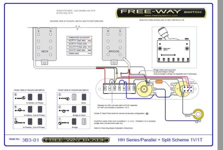
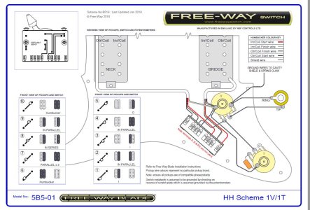
I want to use Dimarzio Evolution Humbuckers. I'm wanting to have 1 3 way switch to swap between the pickups, and an upper 2 way switch to split the coils. I only really need 2 volume knobs and 1 tone knob. I would be grateful for any advice you guys might have, products and diagrams that fit the circumstances especially.
 
Have you tried perusing the dimarzio freeway and seymour duncan websites and diagrams?
 
Thank you for the suggestion, the closest diagram I can find is this one here.

https://d2emr0qhzqfj88.cloudfront.net/s3fs-public/diagrams/2h2ppvsplit1t_3w_all_1.pdf

It's everything I want, but instead of a little switch it's using push pull pots. If this option is a whole lot simpler than figuring out a way to use a switch to coil split both pickups I'll do this. What do you think?
 

Attachments

  • 2h2ppvsplit1t_3w_all_1.pdf
    16.3 KB · Views: 40
So the pickups wires will have to go to the 2 way split switch first, then to the volume knobs, then to the switch, to the tone knob and finally output jack
 
I found another one here that's closer to what I originally envisioned, https://d2emr0qhzqfj88.cloudfront.net/s3fs-public/diagrams/2h2v1pptsplit_3w_all_0.pdf

It's using 1 push pull to activate the coil splits.

Raga, that makes sense, but I don't know where to put which wires if that makes sense, I'm not having any luck finding a diagram that just uses a two way switch to coil split both pickups. Just looking at this diagram, I can't make enough sense of it to actually change it to a 2 way switch.
 
The first diagram you posted would be easy to adapt. If you want to split both humbuckers with one switch you just need a DPDT on on switch and transfer the wiring from the switch portion of the push pulls onto that switch.

Essentially humbucker series link wires connects to the switch common and in one position is joined to ground to split and in the other it is a full humbucker.

If you use two switches you could of course use half of a DPST on on switch or a SPST on on switch for each humbucker.

Example switch.

https://warmoth.com/index.php/hardware/parts/switches/dpst-mini-switch

Bear in mind you need to be aware of the colour codes for the pickups you are using as not all brands are the same.

You will find it explained and how to wire the switch at these links.

https://www.seymourduncan.com/blog/tips-and-tricks/guitar-wiring-explored-switches-part-1
https://www.seymourduncan.com/blog/latest-updates/guitar-wiring-explored-humbucker-internals

For a second humbucker wire it as a mirror image on the other side of the switch per this diagram from the links above.

201_Diag_2.png
 
Ok I drew you up a diagram that I believe is correct (please don't shoot me if it isn't)

gohO56d.jpg
 
@ragamuffin the drawing in terms of the switch for splitting does not look to me quite right. You would need both wires that form the series link of the humbucker soldered to the centre terminal and then one terminal as shown connected to ground.  This is shown at the links I posted above.

EDIT. it appears that is what the diagram of ragamuffin is showing.
 
Thank you to both of you for the quick responses and great help. Just to make sure I have this right, for DiMarzio red is hot, black and white are for "center taps" (Not sure what this means), and green needs to be connected to ground?

Is the black and white wires the one that need to go to the central posts?
 
mime said:
Thank you to both of you for the quick responses and great help. Just to make sure I have this right, for DiMarzio red is hot, black and white are for "center taps" (Not sure what this means), and green needs to be connected to ground?

Is the black and white wires the one that need to go to the central posts?

What kind of humbuckers do you have?

If DiMarzio it is as you describe. What they are calling a center tap is referring to the series link needed to achieve a coil split if shunted to ground. Technically it is a split being called a tap, which technically is something else altogether and the term "center tap" is being used colloquially rather than fully correctly.

Here is a link for different colour codes.

https://www.seymourduncan.com/blog/latest-updates/humbucker-wire-color-translation

 
It's the Dimarzio evolution pair, I really like them in the steve vai Jems.

What exactly about his diagram is incorrect? I see black and whites going to their own central poles from each pickup, and green wires going to the bottom part he labeled with the ground symbol. The hot wires each go to their own volume knob, a ground wire seems to be soldered to the outside of each volume pot, then black wires go to the three way switch, a ground wire comes out, I am assuming this is the one that is sent to the tremolo claw, and the black wire continues from the 3 way to the tone knob, (and the output jack? That's confusing to me), as well as comes out into a capacitor, then grounded to the tone knob, then the output jack has a wire coming out to ground as well?  Please let me know where I have this wrong because I'm almost certain I have it wrong in a couple places.
 
I'm not as electrically gifted as stratman and raggy; all I know is how to follow instructions.  Here's are  examples of a really nice split schemes from freeway.  Basically, I examined all their diagrams and then asked them if they could do something like the attached.  They are pretty responsive.  Just take your time, figure out what you want, ask questions ... you might not get what you want, but if try, sometimes, you get what you need.
 

Attachments

  • 3b3-01 HH Series - Parallel - Split Scheme 1V-1T  for Bagman.JPG
    3b3-01 HH Series - Parallel - Split Scheme 1V-1T for Bagman.JPG
    91.8 KB · Views: 98
  • 5b5-01 scheme b019.jpg
    5b5-01 scheme b019.jpg
    138.8 KB · Views: 94
That looks very well together, so it seems a lot simpler than i originally thought, the black and white wires are wound together and go directly to whatever is determining whether both coils are on or not, and other than that the hot and ground do the exact same thing they would on a normal wiring setup?
 
mime said:
It's the Dimarzio evolution pair, I really like them in the steve vai Jems.

What exactly about his diagram is incorrect? I see black and whites going to their own central poles from each pickup, and green wires going to the bottom part he labeled with the ground symbol. The hot wires each go to their own volume knob, a ground wire seems to be soldered to the outside of each volume pot, then black wires go to the three way switch, a ground wire comes out, I am assuming this is the one that is sent to the tremolo claw, and the black wire continues from the 3 way to the tone knob, (and the output jack? That's confusing to me), as well as comes out into a capacitor, then grounded to the tone knob, then the output jack has a wire coming out to ground as well?  Please let me know where I have this wrong because I'm almost certain I have it wrong in a couple places.

Perhaps it did not look as clear to me on a very small laptop as I am travelling. If black and white are going to the central poles there that is correct for Dimarzios along with green and bare to ground and red to the volume pots.
 
Back
Top