Help needed on unusual custom wiring

agent317

Newbie
Messages
17
Ok, my VIP is around the corner from being delivered, but I'm having some trouble getting the wiring ready. 

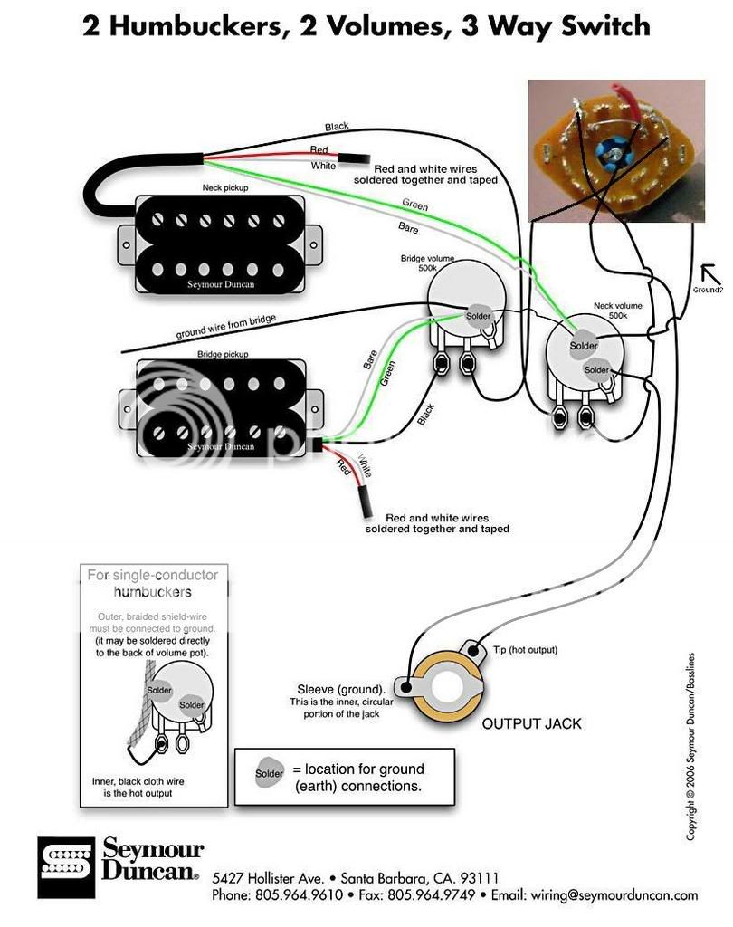
I think I'm going to go with two STK-P1s, the Seymour Duncan Stacked P-90.  Bridge and neck, obviously.  And two volumes.

Here's my problem:  I have a three-way rotary selector switch given to me from a '51 Squier reissue that I want to use as my pickup selector.  Nothing fancy, just bridge-both-neck.  However, I can't find any wiring diagrams for the thing, and the ones I do find are for wild setups (phase coils, single coils, etc.). 

Can anyone give me a hand with the wiring scheme I would need to do this?  SD's website only shows 3-way selectors in blade or switch-styles.  I just don't know enough about the contact points on the rotary to know what needs to go where.

I guess I should post a picture of what I'm working with.  I'll do that when I'm not at work.

Thanks Warmoth community!
 
Yes a picture, or even better a schematic of your switch would be great.
Do you know if the switch is a single or double pole? Lets hope for double, otherwise, I dont think you can select bridge - both- neck.

You can wire to one contact with one pup, and the other pup to the other end of the switch. if you wire both pups to the center, both pups will always be on.

reguardless of switch setting,  You really need a double pole switch.

Good Luck      John
 
Well, since you have a switch from a Squier '51, here's the wiring diagram from a Squier '51!

http://www.squierguitars.com/pdf/diagrams/0325100-wiring.pdf

Since you have a volume for each pickup, put them on each pickup before the selector switch.
 
First, thanks for the help, guys.  I know I promised photos, but work... you know how it is.

I took a look at the wiring schematic you sent, chrisk, and it made things a little better.  I have to admit, I'm a total newb at this, so I'm having a little trouble adjusting in my head what I see as the Fender wiring to the wiring I have.

I'm going to be using two humbuckers, now, and have them here (thanks Spike!).  Bridge is a Seymour Duncan JB Model, neck is a Seymour Duncan Custom.  Both, obviously, have the four-wire connections.

Here's pics of the rotary switch:


l_c089531d54acf427bccf9eadb344ae65.jpg


l_0ca07ca288115cd6d31b42db426161b8.jpg


l_61eb849acf20cfbef2b0c8922aed8f86.jpg


Sorry about being 100% newb, but I appreciate the help, and I'll try not to ask the same question twice.
 
Whoah, that is too intense for me hahaha. I'm a single volume knob kinda guy. :icon_biggrin:
 
If you're just wiring two humbuckers N-Both-Bridge, you can use the wiring diagram already posted, or make life simple and replace with 3 way switch.

If you want to do coil tapping/PRS wiring, scrap that component and order a PRS rotary switch; you can get a full kit with switch, pots, etc. with schematics/diagrams from StewMac.com or guitarelectronics.com.

The only diagram I can find on the net is that '61 Squire which doesn;t give you pinouts on the rest of the switch contacts.
 
Hey Agent, Thats an interesting switch, I've never had the pleasure to see one before, They may be vary popular, I don't know.

What you need to do, is get a meter (VOM) Draw a picture of the switch and take resistance, or a better term is continuity readings between all the posts.

Make a separate drawing, or use a separate color for each diferent switch position. You need to know exactly what opens and closes for each switch position.

I mentioned that you need at least a double pole switch for doing the switching you want. My first impression of that switch is it looks like maybe 4 poles.

Meaning you have plenty of options to switch however you want, After you understand the switch, take your time and think it through as you look at some wiring diagrams. You will figure it out .

Good luck  John
 
based on the 51 squire schematic i can tell you this is a 4 pole 3 position switch. the center 4 lugs are the common 1 for each pole. looking at the diagram ignore every thing but the switch. assume the whit wires are the hot 1 for each pickup. if you have 2 volumes the white wires will come from the center lugs of the pots. if you look at the pot from the bottom with the lugs pointing downwards or tward you the pickup hot will get connected to the left side. the right lug will be grounded as will the pickup ground. the red wire in the diagram that is conected to two commons in the center will go to the tone control or output jack. any more questions?
 
Ok, I've kind of comped together the wiring diagram from SD and the picture of the switch.  And I drew a line into where I think Alfang is talking about the hot output.  Does anyone want to jump in with MS Paint and draw their own completion?

WiringDiagram.jpg
 
Let's get a new summary here as it seems like going through the thread you've changed your mind about the wiring; are you still planning on two volume pots - no tones - the Squire rotary switch? Do you want to coil tap the SDs like in a PRS wiring setup with a rotary switch?
 
No, no coil taps.  Just straight up 2 Hum - 2 Volume - 3 Way Rotary.  Bridge - both - Neck.  Sorry about the confusion.

I would even be happy with Bridge - Dead - Neck.  Get some of those cut-out effects!
 
agent317 i'm a bit of a newb to this whole forum thing. i finished the pic but can't figure out ow to post it.

you got the output right and the ground. you could attach the ground to the switch body if you feel the need. also need a ground for the tail piece/trem claw whichever aplies
the black wire coming from the neck volume gets attached to the 2 pins that are already soldered together for you on the left side of the outer ring of pins as viewed in the photo.
the black wire from the bridge goes to the two similar pins on the right that have the piece of white wire still attached.
this assumes you want to chose the neck when turned clockwise.
you're done.
 
I had to take a second to figure this out, too. 

You have to have the picture online somewhere for it to post here.  Most people use photobucket.com.  I did that, but I've also used myspace, just by posting the picture and finding the link to the actual picture, not the page the picture is on.

Once that's done, copy the URL of the picture, wherever it is (highlight, and press Ctrl-C).  Come here, and click the Insert Image icon.  This will put those img/img tags in the body of your post.  (I would type them out, but they would be read by the computer as html, and wouldn't show up here)

BETWEEN those tags, place your copied link.  (Put the cursor between them, and press Ctrl-V)  Preview it, and the picture should be there if you have a valid address (http://www.xxxxxx.com/picture.jpg, or something to that effect) for the picture.

Wow, that should be a separate post.  I thought it was, but I didn't see it readily available when I was looking on how to post my pictures.

 
agent317 said:
I had to take a second to figure this out, too. 

You have to have the picture online somewhere for it to post here.  Most people use photobucket.com.  I did that, but I've also used myspace, just by posting the picture and finding the link to the actual picture, not the page the picture is on.

Once that's done, copy the URL of the picture, wherever it is (highlight, and press Ctrl-C).  Come here, and click the Insert Image icon.  This will put those img/img tags in the body of your post.  (I would type them out, but they would be read by the computer as html, and wouldn't show up here)

BETWEEN those tags, place your copied link.  (Put the cursor between them, and press Ctrl-V)  Preview it, and the picture should be there if you have a valid address (http://www.xxxxxx.com/picture.jpg, or something to that effect) for the picture.

Wow, that should be a separate post.  I thought it was, but I didn't see it readily available when I was looking on how to post my pictures.


Another way to do it, is to find your picture (where-ever you uploaded it), right-click the picture, choose "Propreties" form the pop-up menu.
Then double-click the "Address" link (see below), then right-click the high-lighted link and choose "copy" from the pop-up menu.

Paste (Right-click + paste, or ctrl-v) this link between image tags ( [ img] xxxxxxxx [ /img] ) and you're all set.

Linking.jpg
 
thanx.

let me know if you still need the diagram. i try to give clear instructions but have a habit of getting wordy. if i made things confusing let me know.
 
Good help DimitriR33, this is what I've put together from your description:

WiringDiagram-1.jpg


Let me know if I have this wrong... 

Now when I ground the wires from the jack, the pots, and the bridge (a Gotoh 510), what can I ground these TO?  It seems like this is a step a lot of people have trouble with, resulting in constant hums. 

To ground the bridge, do I just solder a wire to it and connect it to the ground contact?
 
i'm sorry. i didn't realize there was a second page here. like i said i'm a newb to the whole forum thing. the schematic looks good.
for sheilding many people use conductive paint. i believe sewart macdonald sells it. or you can use a copper tape or foil. i don't know how noisy your normal playing environment is but my strat is only sheilded on the back of the pick guard and it works fine. your bridge route should have a small hole that conects to the control cavity that you can fit a single wire through. just strip maybe 3/4 inch of wire preferably single stranded and run it through this hole before you install the anchor for the bridge. this should make a good contact with the bridge and thus the strings. solder the other end to any pot. you can find some sheilded (coaxial) cable or a twisted pair of wires for the jack and that should be enough shielding but if you want to make sure it's noise proof use the conductive paint of foil tape in the cavity and screw a small wood screw with a wire wraped around it into the jack cavity. solder the other end to the ground connecter on the jack.
i don't know if sheilding the pickup cavities is a must but better safe than sorry. if it's a rear route body paint/foil the pickup cavities. if you mount the pickups direct to the body the screws should do the work for grounding. if you use a mounting ring solder a wire to the backplate of each p/u and wrap the other end around a screw and drive it into the cavity.
sheilding the control cavity is a must! paint/tape it. the pots will ground the cavity just by mounting them. no need for anything extra. also paint or tape the inside of the cover plate for good measure it should make a good enough contact with the cavity paint. if you use the tape you can probably forgo the wire that runs from one pot to the other. i'm not sure about the paint though. i hope this helps and isn't too late
 
Back
Top