DiMarzio 4 conductor wiring question? - 'cuz it has 5 wires ...

Steve_Karl

Hero Member
Messages
1,697
Hey there,
So, these DiMarzio 4 conductor pups actually have 5 wires. The extra one is a braided shield and is NOT connected to the green (ground) wire,
but is only connected to the pickup cover.

There is no mention of the braided shield wire in the manual so I'm going to guess and maybe someone can verify my guess?
So ... I'd guess that
the green ground wire should be connected to the ground on volume pot for the pickup
and
the braided shield should be connected to the ground of the 1/4" output jack?

Any thoughts?

Thanks!

Steve
 
You can connect the shield to the ground wire of the pickup once you decide which one will be ground in your application.
 
generally you'll have all the various possible grounds eventually connected to each other or the 1/4" jack ground lug, so as long as you have continuity in that respect, it shouldn't matter. As long as you don't short it out. But that's a whole 'nother ball game.
 
All I know is to follow the wiring diagram. I remember tying them off like spud and going to the volume pot.
 
The shield or bare wire is generally twisted together with whichever colour is negative for your brand of humbucker pickup and both tinned and soldered to a convenient grounding point.

An exception might be if you are doing some wiring and switching such as out of phase springs to mind. Here you would ground the shield/bare wire to a permanent ground and the negative wire (in this case green) to a switch which in turn has a terminal to ground or not dependent on the position of the switch.
 
Thanks everyone for the feedback.
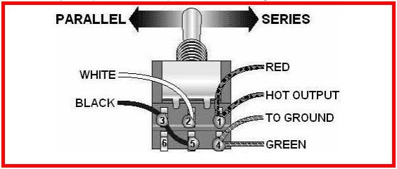
Sorry - I should have been more clear. I'm doing a series / parallel wiring just like this (attached) diagram with the same type of switch. DPDT.
Since the green and the shield aren't connected (tested with multi-meter) I don't think twisting them together is the correct method.
So ... green from pup goes to switch and then a jumper wire from the same terminal to the ground on the volume pot.
I think stratmania has the right idea for this. I'll try it and test.
Pretty close to having it ready to plug in to the amp.
Thanks again.
 

Attachments

  • Untitled-1.jpg
    Untitled-1.jpg
    26.4 KB · Views: 8
ahhh ... the manual calls the braided / shield wire the "bare" wire. That's why I couldn't find it searching the manual for shield or braided.
My mistake for not reading the whole manual word for word.
It says "the bare wire is always soldered to ground".
 
Thanks everyone for the feedback.
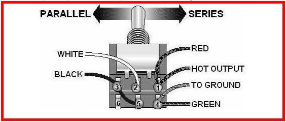
Sorry - I should have been more clear. I'm doing a series / parallel wiring just like this (attached) diagram with the same type of switch. DPDT.
Since the green and the shield aren't connected (tested with multi-meter) I don't think twisting them together is the correct method.
So ... green from pup goes to switch and then a jumper wire from the same terminal to the ground on the volume pot.
I think stratmania has the right idea for this. I'll try it and test.
Pretty close to having it ready to plug in to the amp.
Thanks again.

If that is all you are doing for series and parallel, in both cases the green and bare go to ground so they can be connected. There is no need in this case for them to be separate.
 
Hmmmm. For a 4 way Tele, (not the application here) you have to unsolder the pickup cover ground from the pickup ground. I’ve been wondering if that’s the case here. Cover ground is to master ground. Pickup ground is to switch.
 
Cover ground is to master ground. Pickup ground is to switch.

Yes. After some thought and looking at the photo in the manual - I concluded the same - because if the green and bare were just twisted together,
the ground for the pickup would be disabled when the switch was thrown to the side where the green would not be active.
Too bad the manual isn't more detailed and descriptive.
 
If that is all you are doing for series and parallel, in both cases the green and bare go to ground so they can be connected. There is no need in this case for them to be separate.
Except for one problem. When the switch is thrown to the Series side, where green is not active, the pup would not be grounded. I believe that's the reason to ground the green to the Volume pot and the bare to a more global ground. Then the bare will always be grounded.
 
Hmmmm. For a 4 way Tele, (not the application here) you have to unsolder the pickup cover ground from the pickup ground. I’ve been wondering if that’s the case here. Cover ground is to master ground. Pickup ground is to switch.

That is a different situation. In that case, when in the two pickups are running in series, the negative wire of the neck pickup is connected in series with the bridge pickup and that is why the cover ground has to be separated.

Except for one problem. When the switch is thrown to the Series side, where green is not active, the pup would not be grounded. I believe that's the reason to ground the green to the Volume pot and the bare to a more global ground. Then the bare will always be grounded.

There is no problem. It is grounded per your diagram, green, and ground are both connected to terminal 4. That means, regardless of whether the switch is in the parallel or series position, the overall pickup is grounded. So the bare wire can also be attached to terminal 4.
 
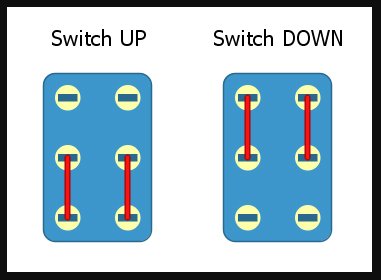
As far as I know - this is how the switch is wired. So in the series position - poles 1 and 4 would be inactive.
 

Attachments

  • DPDT_1.jpg
    DPDT_1.jpg
    60.9 KB · Views: 3
  • Untitled-1.jpg
    Untitled-1.jpg
    26.4 KB · Views: 3
As far as I know - this is how the switch is wired. So in the series position - poles 1 and 4 would be inactive.

As far as those poles making internal switch connections, yes. But that is only part of the story as far as the actual wiring is concerned, 4 has green connected and output to ground in both positions. And 1 has the red hit wire from the pickup also connected to the hot output.

All that is happening in the parallel position by the switch is that black is added to ground and white to hot so that each individual coil is output in a parallel fashion.

In the series position, all the switch is doing is joining black and white together to form the series connection between the coils.

In both switch positions on terminals 1 and 4, the wires connected to each of those terminals are permanently connected, just like joining two wires together. If this was not so the wiring would not work at all.

All of the above is for DiMarzio colours.
 
One thing I like about Freeway is they give you a complete diagram. I'm looking at this and my brain hurts.
 
Back
Top