Leaderboard

Tele series/parallel wiring with non-standard neck pickup

ragamuffin

Hero Member
Messages
1,391
Hey there Warmothians, it's been a while since I've posted much!

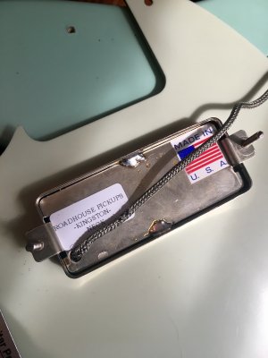
I have a Squier tele that I bought a while back and put in a set of Roadhouse "Ruckus" pickups (tele bridge pup, Supro Kingston goldfoil type neck pickup), which sound pretty great, but I've been wanting to add series/parallel wiring with either a four-way switch or toggle. All of the 4-way schematics that I can find show a standard tele neck pickup with an extra ground wire for the cover: how do I make this work with my kingston neck pickup, which just has a hot lead and a braided shield ground?

Thanks guys!
 
You would need to split the ground wire not to connect to the pickup cover and add another ground wire that does connect to the pickup cover. Then follow one of the diagrams you have found.

 
stratamania said:
You would need to split the ground wire not to connect to the pickup cover and add another ground wire that does connect to the pickup cover. Then follow one of the diagrams you have found.

Thanks, I understand how to add the cover ground for a regular neck pickup, but I'm not sure how to go about it on this one... There isn't an obvious external ground connecting the cover, do I need to take the cover off to do this?


Attachments

  • IMG_2015.jpg
    IMG_2015.jpg
    2 MB · Views: 276
Yes, you'd have to take the cover off and separate the wires as stratamania said. The lead out wire from the coil and the braid may be soldered to the same point on the base plate, if so you'll need to be very careful.

Ken at Roadhouse used to post on here - it might be worth getting in touch to see if he'd do the mod for you if you're not happy to do it yourself. He always seemed like a nice, helpful guy.
 
Now I see that pickup it may be a challenge as the base plate in addition to the cover is conductive. So even when separating them an unintended short between the two could still easily occur. So you may then also need a way to insulate the parts to prevent that occurrence.
 
stratamania said:
Now I see that pickup it may be a challenge as the base plate in addition to the cover is conductive. So even when separating them an unintended short between the two could still easily occur. So you may then also need a way to insulate the parts to prevent that occurrence.

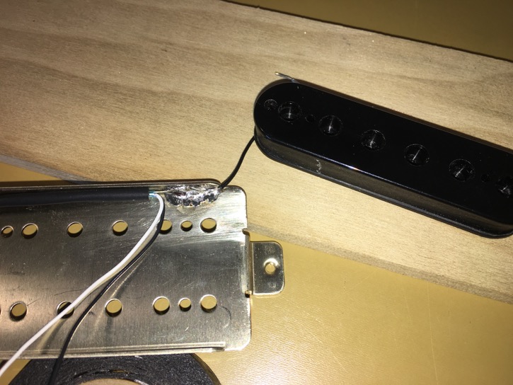
Indeed the cover and baseplate are bonded electrically by the solder that also serves as their structural connection, and they will be grounded by the same braided shield that the coil is using. In this picture you can see the coil and frame connected to the bare wire of a multi-conductor cable; it would be essentially the same with the braid of the single conductor shielded wire in your picture.
Neck%2012.jpeg

You don’t want that braid to become part of the “hot” signal path when you are in series, so in this case you would want to disconnect the coil ground internally and attach a dedicated insulated ground wire for it, leaving the braid to act as the frame/cover ground. If you are not familiar with pickup construction and repair, and if accidentally damaging this one is not an acceptable risk, then your best bet is probably to contact the manufacturer about getting yours modified.
 
Thanks guys, I contacted Ken and he said it might be easier to add a ground wire to the bridge pickup baseplate instead and he'd draw me up a diagram for the wiring, really nice guy!
 
ragamuffin said:
Thanks guys, I contacted Ken and he said it might be easier to add a ground wire to the bridge pickup baseplate instead and he'd draw me up a diagram for the wiring, really nice guy!

I’ve often wondered about that. In the standard configuration the bridge pickup feeds the neck pickup in series; to take advantage of the easier access to bridge pickup ground modification you would change that around so that the neck pickup feeds the bridge. I’ll be very curious to hear how this sounds!
 
So while Ken was really responsive at first he never got back to me with a wiring diagram... Maybe that was a blessing in disguise though, as it forced me to take the time to actually learn how a blade switch and series/parallel wiring works!

With the help of some articles from Fralin and Seymour Duncan and a couple of Youtube videos, I devised my own 4-way switching scheme using a 3-wire bridge pickup. And the crazy part? Nothing blew up!!

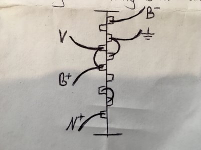
Position 1 is the bridge pickup, pos 2 is parallel, pos 3 is the neck, and pos 4 is series. Attached is my diagram for the switch; B and N stand for bridge and neck, + and - for hot and ground. "V" goes to the volume pot, the ground symbol to ground. The neck pickup ground and bridge pickup baseplate ground are grounded to the pot.

I gained a new sound option for my tele, and learned a lot along the way.
 

Attachments

  • IMG_2035.jpg
    IMG_2035.jpg
    2 MB · Views: 251
ragamuffin said:
So while Ken was really responsive at first he never got back to me with a wiring diagram... Maybe that was a blessing in disguise though, as it forced me to take the time to actually learn how a blade switch and series/parallel wiring works!

With the help of some articles from Fralin and Seymour Duncan and a couple of Youtube videos, I devised my own 4-way switching scheme using a 3-wire bridge pickup. And the crazy part? Nothing blew up!!

Position 1 is the bridge pickup, pos 2 is parallel, pos 3 is the neck, and pos 4 is series. Attached is my diagram for the switch; B and N stand for bridge and neck, + and - for hot and ground. "V" goes to the volume pot, the ground symbol to ground. The neck pickup ground and bridge pickup baseplate ground are grounded to the pot.

I gained a new sound option for my tele, and learned a lot along the way.

Well done! It's amazing what you can figure out with a multimeter and a little time...
 
Back
Top