Super switch wiring - is this possible?

justsomeguy1

Junior Member
Messages
74
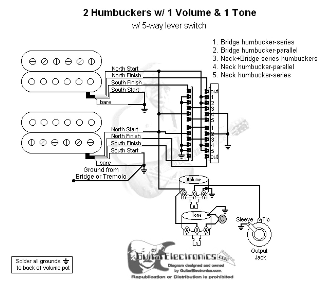
Using an HH pickup configuration with a 5-way super switch I would ideally like the following:

1. Bridge humbucker series
2. Bridge humbucker parallel
3. Bridge and neck both in either split or parallel
4. Neck humbucker parallel
5. Neck humbucker series

Every wiring diagram I come across that has the same position 2 and 4 setup, the position 3 is always bridge and neck in series.

Also every diagram I come accross that has position 3 as bridge/neck both split, positions 2 and 4 are also split.

Is what I'm trying to accomplish with position 3 having bridge/neck both either split or parallel even possible if positions 2 and 4 are parallel wirings?
 
Have you got a diagram close to what you want to do?

If it is just the middle position of an existing diagram you want to have something different it might just be a case of adjusting the wiring.
 
stratamania said:
Have you got a diagram close to what you want to do?

If it is just the middle position of an existing diagram you want to have something different it might just be a case of adjusting the wiring.

This is the diagram that is closest to what I want to achieve. The difference being that I would like position 3 to be the bridge and neck pickups both in either split coil or parallel.

wd2hh5l11_04__72462.1470694481.jpg
 
Just a quick look at it. (it would be easier on the eyes or at least mine if the diagram is in colour)

Anyway to get both humbucker in parallel in position 3 this should work.

Remove the wires in the diagram that on terminals 3 connect between the poles.

Connect a jumper wire from 4 - 3 on each of the top two poles of the diagram. (but not across the poles)

Connect a jumper wire from 2 - 3 on each of the bottom two poles of the diagram. (but not across the poles)

That should do it.
 
stratamania said:
Just a quick look at it. (it would be easier on the eyes or at least mine if the diagram is in colour)

...

That should do it.

I know what you mean, hard to look at. I plan on colorizing it prior to wiring and printing it off.

Here is a copy that I edited with your instructions. Did I interpret them correctly?
 

Attachments

  • wd2hh5l11_04__72462fixed.png
    wd2hh5l11_04__72462fixed.png
    398.5 KB · Views: 114
Yes your adapted diagram looks like what I described.

By the way it will give you in position 3 both humbuckers each wired in parallel and output together in parallel. The diagram originally would give both humbuckers each wired in series and output together in parallel.

 
stratamania said:
By the way it will give you in position 3 both humbuckers each wired in parallel and output together in parallel.

I think I understand. I'm trying to wrap my head around if this is what I am trying to achieve. It's the last part which is confusing me.


stratamania said:
The diagram originally would give both humbuckers each wired in series and output together in parallel.

Unlike a standard HH wiring setup where middle position would give both humbuckers each wired in series, and output... regularly? Haha, unsure of the technical description for how two humbuckers would normally interact when both pickups are selected.
 
justsomeguy1 said:
stratamania said:
By the way it will give you in position 3 both humbuckers each wired in parallel and output together in parallel.

I think I understand. I'm trying to wrap my head around if this is what I am trying to achieve. It's the last part which is confusing me.


stratamania said:
The diagram originally would give both humbuckers each wired in series and output together in parallel.

Unlike a standard HH wiring setup where middle position would give both humbuckers each wired in series, and output... regularly? Haha, unsure of the technical description for how two humbuckers would normally interact when both pickups are selected.

Normally the two coils of a humbucker are joined together in series. If you have two humbuckers like this such as on a Les Paul, if the toggle switch is in the middle so both pickups are being output together, each individual pickup still has its coils wired together in series but the output of the two series wired humbuckers is output to the jack in parallel.

I mention it as usually two humbuckers on together would be as I have just described and like the original unaltered diagram.

 
stratamania said:
Normally the two coils of a humbucker are joined together in series. If you have two humbuckers like this such as on a Les Paul, if the toggle switch is in the middle so both pickups are being output together, each individual pickup still has its coils wired together in series but the output of the two series wired humbuckers is output to the jack in parallel.

I mention it as usually two humbuckers on together would be as I have just described and like the original unaltered diagram.

Ok perfect thank you again, that helped a lot. Seems like the position 3 being parallel individually and also combined is what I was thinking about initially.

 
justsomeguy1 said:
stratamania said:
Normally the two coils of a humbucker are joined together in series. If you have two humbuckers like this such as on a Les Paul, if the toggle switch is in the middle so both pickups are being output together, each individual pickup still has its coils wired together in series but the output of the two series wired humbuckers is output to the jack in parallel.

I mention it as usually two humbuckers on together would be as I have just described and like the original unaltered diagram.

Ok perfect thank you again, that helped a lot. Seems like the position 3 being parallel individually and also combined is what I was thinking about initially.

Ok post an update of how you got on when you wired it up. Don't breathe the solder fumes  :glasses9:
 
I’ve got a freeway switch diagram that gets you close.  I’ll see if I can dig it out.
 
This is close
 

Attachments

  • 5B5-01 Scheme B019 (1) (1).pdf
    511 KB · Views: 112
I think this is what you're looking for.

https://d2emr0qhzqfj88.cloudfront.net/s3fs-public/diagrams/2hum1v1t_ep1112parallel_0.pdf
 
Back
Top