The rain has cancelled this weekend's camping trip, so I had some time to post this in the hopes it will be useful for trouble-shooting an annoying 60 Hertz buzz problem. I know there are varying opinions on guitar wiring on the web, but this is just how I do it. I get no more hum/hiss from a P90 than I do from a humbucker, and I have a guitar with one of each that allows me to toggle between the two.
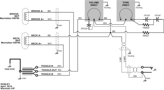
For my latest Warmoth build I drew a schematic showing the complete "signal return" (RTN) circuit. I consider this separate from the "guitar chassis ground" (GND). This is the key to draining unwanted noise away from the signal.
Eventually the RTN and GND circuits must be combined as they share the outer braid of a coax cable to the amplifier. Ideally this should happen at a single point as close as possible to the signal output jack.
If this is done, then the GND can be used to form a Faraday cage by making ground loops which are a good thing...an E-Field antenna to catch that buzz and drain it away from your signal. The GND connections include the guitar's bridge (and by extension the strings and tuners), the backs of potentiometers, switch ground tabs and pickup covers (which requires a separate drain wire from the pickup return wire.)
The RTN circuit should have no loops, as these could form a loop antenna capable of introducing noise to the signal. A star connection is ideal. The RTN circuit includes the pickup signal return wires to the magnet coils, the volume knob return, the tone knob/capacitor circuit return and the single connection point to the chassis ground at the output jack.
Thankfully, guitar wiring is very forgiving so there is no one "right way" to do it. Hopefully the method I described helps somebody solve a problem somewhere, and if it does please post something and let me know how it went!
(There's no preview of the photos so I hope the image size turns out okay.)